84
1
2
4
5
6
7
M6=10 Nm
M8=18 Nm
M10=50 Nm
3
a
b
≤ 4.0 kW
≥ 5.5 kW
- A -
EVMS 1 - 3 - 5 - 10 - 15 - 20
1
2
3
4
5
6
7
8
M6=15 Nm
M8=25 Nm
M10=50 Nm
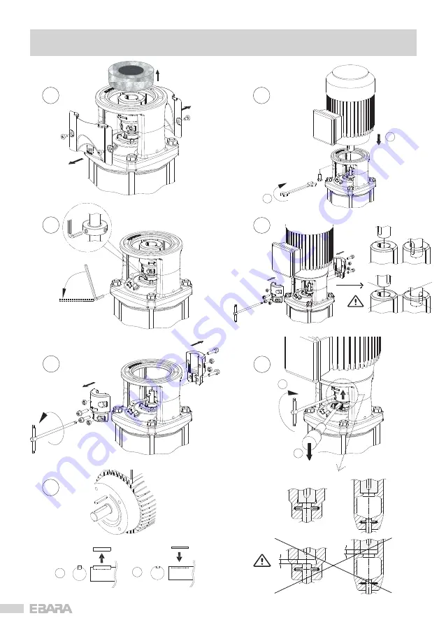
Fit the half key into the motor
shaft.
Note: Ensure the half key does
not protrude.
Set the motor vertically with
its shaft downwards and
position it on the pump.
Loosen off the
coupling bolts.
Insert and evenly tighten the 4
motor bolts.
Check that the 3 drive collar
grub screws are loose.
Using two screw drivers
lever between the coupling
and motor mount & lift up
so the coupling is snug
against the shaft end;
tighten the coupling bolts
evenly to the specified
torque.
Remove motor
shaft key.
Standard assembly is for the
terminal box to be positioned
over the discharge.
(see bottom of page below)
Assembly & installation should
only be carried out by suitably
experienced & qualified persons.
!
Air bleed
valve.
3/8 Plug
Fill/Prime
(Pressure sensor)
Standard assembly is for the
terminal box to be positioned
over the discharge.
For convenience of power cable
connection, the terminal box can
be positioned at 90° increments.
Refer to Sect 9 - Electrical
Connection - in the O&I Manual
for details.
Fitting of motor & initial start up
EVMS ()
Vertical Multistage Pumps
Read the Operating & Instruction
Manual supplied with the pump.
!
Extracted from the Operating & Instruction Manual
Page 1/2
M6=10 Nm
M8=20 Nm
M12=40 Nm
M16=70 Nm
a
b
360°
a
b
Содержание EVMS 1
Страница 85: ...85 12 13 14 9 8 10 11 A EVMS 1 3 5 10 15 20 3 Nm...
Страница 87: ...87 A EVMS 32 45 64 90 without ball bearing 9 10 11 12 13 14 15 5 Nm 2 min...
Страница 88: ...88 A EVMS 32 45 64 90 with ball bearing 2 min 1 2 3 4 5 7 6 M8 20 Nm M12 40 Nm M16 70 Nm...
Страница 91: ...91 E EVMS 1 3 5 10 15 20 4 kW 1 2 3 4 5 6 7 8 9 10 3 Nm M6 10 Nm 11 12...
Страница 92: ...92 E EVMS 1 3 5 10 15 20 5 5 kW 1 2 3 4 5 6 7 8 9 10 11 12 3 Nm M8 18 Nm M10 50 Nm...
Страница 97: ...97...
Страница 98: ...98...
Страница 99: ...99...


