


40
Step 5 - Standard application
POWERXL DM1 SERIES ADJUSTABLE FREQUENCY DRIVES
PUB53696—August 2020 www.eaton.com
Table 11. Inputs (Cont.).
P2.4.2
b
AI signal range
ID 175
Minimum value:
N.A.
Maximum value:
N.A.
Default value:
0
Options:
0 = 0-100%/0-20 mA/0-10 V.
1 = 20-100%/4-20 mA/2-10 V.
Description:
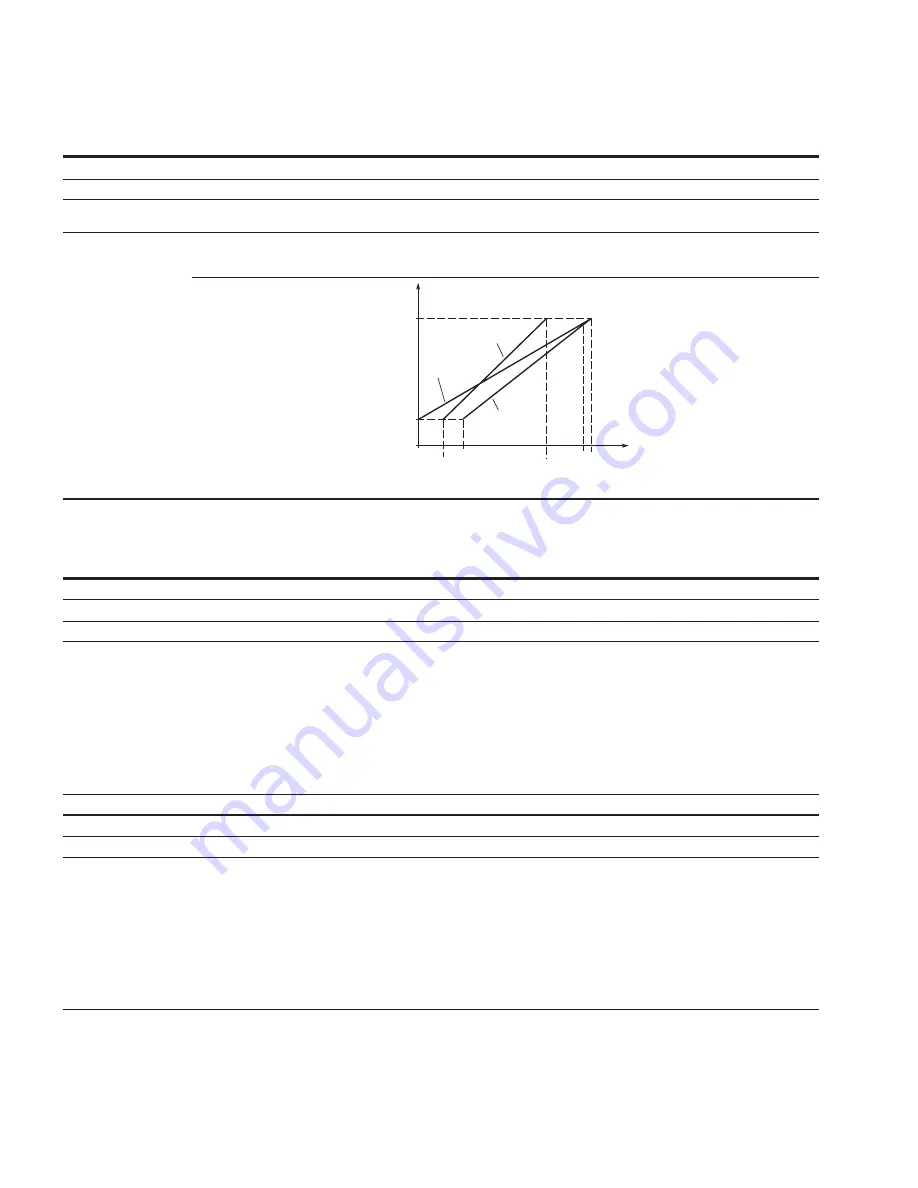
With this parameter, you can select the analog input 1 signal range.
For selection “Customized,” see “AI Custom Min” and ”AI Custom Max”, this enables a customized signal range.
Output
Frequency
AI Ref.
Scale Min.
Value
0
20 mA
AI2
(Term. 3,4)
AI1
Custom
Min.
4 mA
AI1 Signal
Range = Custom
AI2 = 0 – 100%
AI Ref.
Scale Max.
Value
AI1 Signal
Range
= 0
AI1 Signal
Range = 1
AI2 = 20 – 100%
AI1
Custom
Max.
a
Parameter value can only be changed after the drive has stopped.
b
Parameter value will be set to be default when changing macros.
Table 12. Outputs (Cont.).
P3.1 - Digital output.
P3.1.1
b
RO1 function
ID 152
Minimum value:
N.A.
Maximum value:
N.A.
Default value:
2
Options:
0 = Not used - no action.
1 = Ready - drive is ready for operation.
2 = Run - drive is running.
3 = Fault - drive is faulted.
4 = Fault invert - drive is not faulted.
5 = Warning - drive has a warning message.
6 = Reverse - drive is outputting reverse phase rotation.
7 = At speed - output frequency has reached the set reference.
8 = Zero frequency - drive output is at zero frequency.
24 = STO fault output - safe torque off input is activated.
26 = Remote control - remote is the control place.
37 = PI sleep - PI controller is in a sleep state.
Description:
Defines the function associated with changing the state of relay output 1.
P3.1.4
b
RO2 function
ID 153
Minimum value:
N.A.
Maximum value:
N.A.
Default value:
3
Options:
0 = Not used - no action.
1 = Ready - drive is ready for operation.
2 = Run - drive is running.
3 = Fault - drive is faulted.
4 = Fault invert - drive is not faulted.
5
= Warning - drive has warning message.
6 = Reverse - drive is outputting reverse phase rotation.
7 = At speed - output frequency has reached the set reference.
8 = Zero frequency - drive output is at zero frequency.
24 = STO fault output - safe torque off input is activated.
26 = Remote control - remote is the control place.
37 = PI sleep - PI controller is in a sleep state.
Description:
Defines the function associated with changing the state of relay output 2.
.