background image

11-1

EATON

Powerware

®

9390 UPS (100–160 kVA) Installation and Operation Manual

S

164201554 Rev E

powerware.com

Chapter 11

Using Features and Options

The many standard features of your UPS system provide consistent, economical, and

dependable power protection. In addition, you can add available options to enhance the

performance of your system. This chapter provides descriptions of some of the features

and options introduced earlier in this manual. For location of the customer interface panel

and terminals and for terminal wiring information, see:

Drawing 164201554-6 on page A-27

Drawing 164201554-8 starting on page A-33

11.1 Building Alarm Monitoring

This standard feature lets you connect the UPS to your building alarms, such as smoke

detectors or overtemperature alarms. The customer interface terminals for external

connections are located inside the UPS. You should use twisted-pair wires for each alarm

input and common.

The building alarms can be programmed to display the alarm functional name.

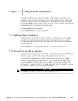
11.2 General Purpose Relay Contact

One general purpose relay contact is provided as a standard feature on the UPS. The alarm

contact is located inside the UPS on the customer interface terminal board.

You can use a normally-closed or normally-open contact. If the state of the contact

changes from the state you specify as normal, a signal is issued. You can connect this

contact to equipment at your facility (such as a light or an alarm bell) to let you know

when an alarm is active on the UPS. This feature is useful if the UPS is located in a remote

area where the UPS horn may not be heard immediately.

C A U T I O N

Contacts should not be operated in excess of 120 Vac @ 5A maximum.

Содержание Powerware 9390-160/100

Страница 1: ...Powerware 9390 UPS 100 160 kVA Installation and Operation Manual...

Страница 2: ...ent generates uses and can radiate radio frequency energy and if not installed and used in accordance with the instruction manual may cause harmful interference to radio communications Operation of th...

Страница 3: ...3 1 Preliminary Installation Information 3 1 3 2 UPS Cabinet Installation 3 1 3 2 1 Unloading the Powerware 9390 UPS Cabinet from the Pallet 3 2 3 2 2 Battery Cabinet Installation 3 5 3 2 3 Integrated...

Страница 4: ...nstalling a Relay Interface Module II 6 4 6 5 Installing a Supervisory Contact Module II 6 6 Section II Operation 7 Understanding UPS Operation 7 1 7 1 Looking Inside the UPS System 7 1 7 2 Single Mod...

Страница 5: ...ery Cabinets 8 2 8 2 2 Integrated Distribution Cabinet 8 2 8 2 3 Integrated Accessory Cabinet IAC B IAC T and IAC D 8 3 8 2 4 Powerware Hot Sync Parallel System 8 3 8 2 5 Sync Control 8 3 8 2 6 Option...

Страница 6: ...wer off Switch 10 7 10 2 Multiple Module Parallel Operation 10 8 10 2 1 Starting the Parallel System in Normal Mode 10 8 10 2 2 Starting the Parallel System in Bypass Mode 10 9 10 2 3 Transfer Paralle...

Страница 7: ...ventive Maintenance 14 2 14 2 1 DAILY Maintenance 14 2 14 2 2 MONTHLY Maintenance 14 3 14 2 3 ANNUAL Maintenance 14 3 14 2 4 BATTERY Maintenance 14 3 14 3 Maintenance Training 14 3 15 Product Specific...

Страница 8: ...Table of Contents vi EATON Powerware 9390 UPS 100 160 kVA Installation and Operation Manual S 164201554 Rev E powerware com This page intentionally left blank...

Страница 9: ...hrough the UPMs in Battery Mode Parallel 7 14 Figure 9 1 UPS Control Panel 9 1 Figure 9 2 Parts of the LCD 9 2 Figure 9 3 Main Menu and Mimic Screen Normal Mode 9 3 Figure 9 4 Active Events Screen 9 4...

Страница 10: ...X Meter Screen 9 32 Figure 9 37 Output Current Load Unit X Meter Screen 9 32 Figure 9 38 System Setup Level 0 Screen 9 33 Figure 9 39 Contrast Adjust Screen 9 34 Figure 9 40 Versions Screen 9 35 Figur...

Страница 11: ...tion equipment due to unexpected power problems The Powerware 9390 UPS continually monitors incoming electrical power and removes the surges spikes sags and other irregularities that are inherent in c...

Страница 12: ...erware Hot Sync parallel system with three UPS modules one to four battery cabinets for each UPS and an optional module tie cabinet Two capacity one redundant 2 1 Three capacity 3 0 Powerware Hot Sync...

Страница 13: ...UPS System describes how to install and wire the UPS cabinet and optional equipment Chapter 4 Batteries provides battery safety and installation information Chapter 5 Installing a Remote Emergency Pow...

Страница 14: ...dures that apply to the UPS system being installed or operated 1 3 Conventions Used in This Manual This manual uses these type conventions Bold type highlights important concepts in discussions key te...

Страница 15: ...all this UPS in a temperature and humidity controlled indoor environment free of conductive contaminants Ambient temperature must not exceed 40 C 104 F Do not operate near water or excessive humidity...

Страница 16: ...0 UPS Sidecar Installation and Operation Manual 164201586 or the Powerware 9390 Sync Control Installation and Operation Manual 164201571 as applicable for the following additional information Installa...

Страница 17: ...1 1 EATON Powerware 9390 UPS 100 160 kVA Installation and Operation Manual S 164201554 Rev E powerware com Section I Installation...

Страница 18: ...1 2 EATON Powerware 9390 UPS 100 160 kVA Installation and Operation Manual S 164201554 Rev E powerware com This page intentionally left blank...

Страница 19: ...ly a two week notice is required to reserve a preferred startup date 2 1 Creating an Installation Plan Before installing the UPS system read and understand how this manual applies to the system being...

Страница 20: ...breakers must be provided one for the UPS and one for the maintenance bypass input DO NOT use one feed or a single feeder breaker to supply both the UPS and the maintenance bypass For external wiring...

Страница 21: ...dence of damage during transit C A U T I O N Do not install a damaged cabinet Report any damage to the carrier and contact your Eaton service representative immediately 2 Use a forklift or pallet jack...

Страница 22: ...lete 4 Remove the protective covering from the cabinet 5 Remove the packing material and discard or recycle in a responsible manner 6 After removing the protective covering inspect the contents for an...

Страница 23: ...ion place them in front of the UPS See Table A on page A 3 for equipment weight and point loading Details about control wiring are provided in each procedure for connecting options and features Drawin...

Страница 24: ...t NOTE Verify that the forklift or pallet jack is rated to handle the weight of the cabinet see Table A on page A 3 for cabinet weight 2 Unfasten the front door latch and swing the door open see Figur...

Страница 25: ...Installation and Operation Manual S 164201554 Rev E powerware com Shipping Bracket Bolts Front View Pallet Vented Front Doors Front Shipping Bracket Shipping Bracket Bolts Removable Skid Skid Bolts Fi...

Страница 26: ...re 9390 UPS 100 160 kVA Installation and Operation Manual S 164201554 Rev E powerware com Rear Shipping Bracket Pallet Rear View Shipping Bracket Bolts Shipping Bracket Bolts Figure 3 2 Removing Rear...

Страница 27: ...tallation location 11 If installing the cabinet permanently retain the shipping brackets and hardware otherwise discard or recycle the pallet and shipping brackets in a responsible manner 12 If perman...

Страница 28: ...a debris shield covering the ventilation grill on top of the unit Do not remove the debris shield until installation is complete However remove the shield before operating the UPS Once the debris shie...

Страница 29: ...ety shield panel and remove the panel to gain access to the top wiring entry Retain the hardware for later use Remove the top conduit plate from its storage location on the top of the UPS Identify all...

Страница 30: ...IAC proceed to Step 15 otherwise proceed to Step 18 15 Route and connect the output cable between the UPS cabinet and the IDC or IAC Refer to the applicable IDC or IAC installation and operation manua...

Страница 31: ...ingle feed system proceed to Step 9 if wiring a dual feed system proceed to Step 11 8 Connect phase A B C and Neutral if required input power wiring from the utility source to the bypass input termina...

Страница 32: ...dule tie cabinet See Appendix A for UPM wiring and termination requirements and wiring access information 19 Proceed to paragraph 3 2 6 3 20 Connect phase A B and C and Neutral if required power wirin...

Страница 33: ...and swing the door open 3 If not already removed remove the doors Remove the retaining screws located inside each door at the top and bottom hinge pivot points then lift the door off Retain the hardw...

Страница 34: ...screws located inside each door at the top and bottom hinge pivot points then lift the door off Retain the hardware for later use 4 Remove the screws securing the control panel door and swing the doo...

Страница 35: ...previous steps Secure with the retained hardware 19 Close the control panel door and secure with the retained hardware 20 Reinstall the doors removed previously and secure with the retained hardware...

Страница 36: ...1 become void This service is offered as part of the sales contract for the UPS Contact service in advance usually a two week notice is required to reserve a preferred startup date 3 4 Completing the...

Страница 37: ...ning equipment is installed and operating correctly The area around the installed UPS system is clean and dust free It is recommended that the UPS be installed on a level floor suitable for computer o...

Страница 38: ...terminated The bypass source feeding the optional bypass of the parallel tie cabinet and the UPMs is from the same source of supply and is a four wire wye configuration Neutral conductors are install...

Страница 39: ..._____________________ _________________________________________________________________________ _________________________________________________________________________ ______________________________...

Страница 40: ...Installing the UPS System 3 18 EATON Powerware 9390 UPS 100 160 kVA Installation and Operation Manual S 164201554 Rev E powerware com This page intentionally left blank...

Страница 41: ...tteries 4 Wear rubber globes and boots ELECTRIC ENERGY HAZARD Do not attempt to alter any battery wiring or connectors Attempting to alter wiring can cause injury C A U T I O N The installation of bat...

Страница 42: ...battery and battery rack manufacturer s instructions 4 3 Recycling the Used Battery or UPS Contact your local recycling or hazardous waste center for information on proper disposal of the used battery...

Страница 43: ...to punch conduit holes see Drawing 164201554 6 on page A 27 NOTE The REPO switch must be a latching type switch with a dedicated circuit 1 Securely mount the REPO station Recommended locations include...

Страница 44: ...el and remove the panel to gain access to the bottom conduit landing plate 10 To locate the appropriate terminals and review the wiring and termination requirements see Figure 5 1 and Drawing 16420155...

Страница 45: ...tion to trip circuitry of upstream protective devices A normally open NO contact is provided between terminals 6 and 7 of REPO as shown in Figure 5 1 REPO switch wiring must be in accordance with UL C...

Страница 46: ...Installing a Remote Emergency Power off Switch 5 4 EATON Powerware 9390 UPS 100 160 kVA Installation and Operation Manual S 164201554 Rev E powerware com This page intentionally left blank...

Страница 47: ...Interface Module II or a Supervisory Contact Module II to the UPS Plug in Terminal Block J3 Figure 6 1 Powerware Hot Sync CAN Bridge Card NOTE Only one Powerware Hot Sync CAN Bridge Card can be instal...

Страница 48: ...e listed in paragraph 6 1 3 If not already removed remove the doors Remove the retaining screws located inside each door at the top and bottom hinge pivot points then lift the door off Retain the hard...

Страница 49: ...h the retained hardware 16 Close the doors and secure the latch 6 3 Installing a Remote Monitor Panel II To install RMP II wiring perform the following procedure 1 Verify the UPS system is turned off...

Страница 50: ...and the RMP II is not present the RMP II performs a self test all indicators flash and the horn beeps at one second intervals If the self test occurs check all harness connectors and the fuse for prop...

Страница 51: ...om the critical bus by facility planners or the customer 8 Install 120 Vac power wiring from the critical bus to the RIM II See Drawing 164201554 8 starting on page A 33 for terminal location and wiri...

Страница 52: ...e the UPS cabinet top or bottom conduit landing plate to drill or punch conduit holes see Drawing 164201554 6 on page A 27 4 Remove the X Slot conduit landing plate from the UPS cabinet to drill or pu...

Страница 53: ...minal assignments and Drawing 164201554 8 on page A 33 for terminal block location System Normal No Redundancy On Generator Bypass Not Available On Battery UPS Alarm On Bypass Shutdown Imminent TB2 Fi...

Страница 54: ...Installing Options and Accessories 6 8 EATON Powerware 9390 UPS 100 160 kVA Installation and Operation Manual S 164201554 Rev E powerware com This page intentionally left blank...

Страница 55: ...6 9 EATON Powerware 9390 UPS 100 160 kVA Installation and Operation Manual S 164201554 Rev E powerware com Section II Operation...

Страница 56: ...6 10 EATON Powerware 9390 UPS 100 160 kVA Installation and Operation Manual S 164201554 Rev E powerware com This page intentionally left blank...

Страница 57: ...nout blackout overvoltage undervoltage and out of tolerance frequency conditions The basic system consists of a rectifier battery converter inverter monitoring operation control panel integrated commu...

Страница 58: ...and or parallel capacity operation see paragraphs 7 2 and 7 3 7 2 Single Module Reverse Transfer RT A single module operates independently to support an applied load from the inverter providing condit...

Страница 59: ...rrent mode of operation The UPS switches operating modes in response to these system events A command is an intervention that is externally initiated by an operator or by some site action A command ca...

Страница 60: ...system is derived from a utility input source through the rectifier input contactor K1 The front panel displays Normal indicating the incoming power is within voltage and frequency acceptance windows...

Страница 61: ...pulse width modulation PWM to produce a regulated and filtered AC output The AC output of the inverter is delivered to the system output through the output contactor K3 If the utility AC power is int...

Страница 62: ...e the output of the system is not protected from voltage or frequency fluctuations or power outages from the source Some power line filtering and spike protection is provided to the load but no active...

Страница 63: ...er The transfer occurs in less than 4 mS quarter cycle to ensure that the output load is not interrupted The static switch remains on until either the inverter is able to support the system output or...

Страница 64: ...h to supply the DC output current required to support the inverter The input contactor K1 opens and the battery instantaneously supplies energy to the battery converter The converter either bucks or b...

Страница 65: ...time 7 3 Multiple Module Parallel System Parallel operation extends the normal operation of Powerware 9390 UPS units by offering increased capacity and or redundant capability The parallel system con...

Страница 66: ...ical load is directly supported by utility power through the continuous duty static bypass switch in each UPM The UPMs continually monitor themselves and the incoming utility power and automatically s...

Страница 67: ...g in Normal mode Main Power Flow UPM 1 UPM 2 UPM 3 UPM 4 Output to Critical Load Battery UPM Input Module Tie Cabinet UPM 1 Output Bypass Input UPM 2 Output UPM 3 Output UPM 4 Output Battery Battery B...

Страница 68: ...electrical power through the parallel system when operating in Bypass mode Main Power Flow UPM 1 UPM 2 UPM 3 UPM 4 Output to Critical Load Battery UPM Input Module Tie Cabinet UPM 1 Output Bypass Inpu...

Страница 69: ...e critical load to the bypass source and requires operator intervention to transfer Bypass mode is a normal operating mode not an alarm condition However if the parallel system is unable to return to...

Страница 70: ...Flow UPM 1 UPM 2 UPM 3 UPM 4 Output to Critical Load Battery UPM Input Module Tie Cabinet UPM 1 Output Bypass Input UPM 2 Output UPM 3 Output UPM 4 Output Battery Battery Battery Closed Open Breakers...

Страница 71: ...y and rectifier input current limit alarms may be seen for a short time due to the current required to recharge the batteries 7 4 Functional Description The UPS is a true online double conversion unit...

Страница 72: ...the actual battery run time is determined and the actual battery run time is displayed After the float period is completed the charger is disconnected and the batteries are allowed to rest for 672 ho...

Страница 73: ...tatus See Chapter 11 Using Features and Options for additional information 8 1 2 2 Alarm Contact One alarm contact is provided for connection to equipment at the facility such as a light an audible al...

Страница 74: ...in accordance with Class 1 wiring methods Line up and match battery cabinets are wired through the side panels of the units Optional X Slot connectivity cards are quickly installed at the front of th...

Страница 75: ...addition when one UPM is taken out of service for maintenance or is not operating properly a redundant UPM continues to supply uninterrupted power to the critical load A Powerware Hot Sync Computer A...

Страница 76: ...pment and the customer s monitor This option is described further in Chapter 11 Using Features and Options 8 3 Symbols Controls and Indicators The following are examples of symbols used on the UPS or...

Страница 77: ...Y KEY TO CONTINUE Figure 9 1 UPS Control Panel The control panel consists of the following A liquid crystal display LCD 1 A horizontal row of pushbutton switches 2 A vertical column of status indicato...

Страница 78: ...e For more information about alarms and notices see Chapter 12 Responding to System Events B The information area contains data about UPS status and operations C The menu bar lists the titles of the a...

Страница 79: ...me for the time stamp configure the UPS serial communication ports and view the firmware version numbers LOAD OFF De energizes the critical load and powers down the UPS Returns to Main Menu and Mimic...

Страница 80: ...s that are currently active The most recent event is listed first As events clear they are removed from the Active System Events listing Figure 9 4 shows the Active Events screen To scroll through the...

Страница 81: ...lowing groups User and service status User instruction User alarm Check UPS Schedule service UPS shutdown Service alarm The end of the log the most recent events appears when you display the screen an...

Страница 82: ...e main menu bar to display the Unit Meter screens Figure 9 6 through Figure 9 10 show the Unit Meter screens To scroll through the meter screens press the or pushbuttons on the menu bar The current UP...

Страница 83: ...ty source as well as the kVA kW and power factor measurements INPUT UNIT V1 V2 V3 KVA KW PF I1 I2 I3 FREQ LEAD UNIT SYSTEM Figure 9 7 Unit Input Meter Screen The Bypass screen shows the bypass input v...

Страница 84: ...be set up by an authorized Eaton Customer Service Engineer When battery life decreases to less than 20 Check Battery is displayed VDC IDC TIME REMAINING V A MINUTES BATTERY UNIT UNIT SYSTEM TEMPERATU...

Страница 85: ...mini CSB is installed The battery discharge log collects information when the unit is on battery The Battery Discharge Log Summary screen displays the total number of times since the last log reset t...

Страница 86: ...nd the end voltage of the battery for that discharge period If no events have occurred the screen will display LOG EMPTY Figure 9 12 shows the Battery Discharge Log screen To scroll through the indivi...

Страница 87: ...Demand Log Summary screen displays the number of total times the limit has been exceeded since the last log reset the date of the last log reset the maximum KW reading and the total time over the lim...

Страница 88: ...al KWH used during the interval and the number of times over limit during the interval If no events have occurred the screen displays LOG EMPTY Figure 9 14 shows the KW Demand Log screen To scroll thr...

Страница 89: ...n 1 The Current KW Demand Log Setup screen 1 displays the current user defined log settings If no log settings are configured the screen will display KW LOG DISABLED Figure 9 15 shows the Current KW D...

Страница 90: ...en can be used to set up or change the time interval and maximum level log settings Figure 9 16 shows the Current KW Demand Log Setup screen 2 Use the or pushbuttons to highlight the setup function sc...

Страница 91: ...e Interval Monitored Setup screen allows the time duration of the event being monitored to be changed Figure 9 17 shows the Time Interval Monitored Setup screen Use the or pushbuttons to select the ch...

Страница 92: ...another time interval or abort the change Figure 9 18 shows the Time Interval Monitored Setup Save screen Press SAVE RETRY or ABORT If SAVE or ABORT is pressed the action is completed and the Current...

Страница 93: ...creen The Maximum Level KW Setup screen allows the KW limit of the event being monitored to be changed Figure 9 19 shows the Maximum Level KW Setup screen Use the or pushbuttons to select the characte...

Страница 94: ...imit retry another KW limit or abort the change Figure 9 20 shows the Maximum Level KW Setup Save screen Press SAVE RETRY or ABORT If SAVE or ABORT is pressed the action is completed and the Current K...

Страница 95: ...the individual phase currents or is a limit defined for each phase individually In the first case an event is logged if the average across the phases exceeds the defined limit within a given time per...

Страница 96: ...dividual phase option is selected the phases that exceeded the limit will also be displayed If no events have occurred the screen will display LOG EMPTY Figure 9 22 and Figure 9 23 show the Maximum Cu...

Страница 97: ...Press the SETUP pushbutton on the Maximum Current Log Summary Menu bar to display the Maximum Current Log Setup screen 1 The Maximum Current Log Setup screen 1 displays the current user defined log se...

Страница 98: ...al the maximum percent of load and the calculation method three phase average or individual phases log settings Figure 9 25 shows the Maximum Current Log Setup screen 2 Use the or pushbuttons to highl...

Страница 99: ...Interval Monitored Setup screen allows the time duration of the event being monitored to be changed Figure 9 26 shows the Time Interval Monitored Setup screen Use the or pushbuttons to select the cha...

Страница 100: ...another time interval or abort the change Figure 9 18 shows the Time Interval Monitored Setup Save screen Press SAVE RETRY or ABORT If SAVE or ABORT is pressed the action is completed and the Maximum...

Страница 101: ...he Maximum of Full Load Setup screen allows the full load limit of the event being monitored to be changed Figure 9 28 shows the Maximum of Full Load Setup screen Use the or pushbuttons to select the...

Страница 102: ...retry another load limit or abort the change Figure 9 29 shows the Maximum of Full Load Setup Save screen Press SAVE RETRY or ABORT If SAVE or ABORT is pressed the action is completed and the Maximum...

Страница 103: ...limit of the event being monitored to be changed Figure 9 30 shows the Calculation Method Setup screen Use the or pushbuttons to highlight the calculation method desired then press the SELECT pushbut...

Страница 104: ...e to neutral However an authorized Eaton Customer Service Engineer can change the screens to display the voltage phase to phase A B B C C A Press the METERS pushbutton on the main menu bar to display...

Страница 105: ...frequency being supplied by the UPS as well as the kVA kW and power factor measurements for the total system The displayed voltages and frequency are the highest measured value of all units The displ...

Страница 106: ...splayed in the information area of the screen To return to the present Unit Meter screens press the UNIT pushbutton on the menu bar NOTE In the following figures X equals the unit number selected from...

Страница 107: ...VA kW and power factor measurements for the selected unit INPUT UNIT X V1 V2 V3 KVA KW PF I1 I2 I3 FREQ LEAD UNIT SYSTEM Figure 9 34 Input Unit X Meter Screen The Bypass screen shows the bypass input...

Страница 108: ...n authorized Eaton Customer Service Engineer When battery life decreases to less than 20 Check Battery is displayed VDC IDC TIME REMAINING V A MINUTES BATTERY UNIT X UNIT SYSTEM TEMPERATURE DEGREES C...

Страница 109: ...word to access Level 1 functions see paragraph 9 2 9 No password is necessary to access Level 0 functions Set the screen contrast Show the firmware versions installed Identify the unit type Figure 9 3...

Страница 110: ...Contrast Adjust screen Figure 9 39 shows the Contrast Adjust screen Use the or pushbuttons to adjust the contrast for the LCD When the contrast adjustment is complete press the SAVE pushbutton Once t...

Страница 111: ...s the or pushbuttons on the menu bar To return to the System Setup screen press the pushbutton DSP DISPLAY MINI CSB 57 00 0 54 GATE DRIVE 3 00 0 00 VERSIONS PLD 1 BOOTLOADER 0 00 Figure 9 40 Versions...

Страница 112: ...lect ENTER PASSWORD from the System Setup Level 0 menu to display the Enter Password screen Figure 9 42 shows the Enter Password screen Use the or pushbuttons to select the password character position...

Страница 113: ...functions are available Figure 9 43 shows the System Setup Level 1 screen Use the or pushbuttons to highlight the setup function screen desired then press the SELECT pushbutton to display the functio...

Страница 114: ...en The Change Password screen allows the System Setup Level 1 password to be changed Figure 9 44 shows the Change Password screen Use the or pushbuttons to select the password character position Use t...

Страница 115: ...e new password retry another password or abort the password change Figure 9 45 shows the Change Password Save screen Press SAVE RETRY or ABORT If SAVE or ABORT is pressed the action is completed and t...

Страница 116: ...allows the selection of either month day year or day month year formats for display on the screen and for logging events in the Event and History Logs Figure 9 46 shows the Time Format screen Use the...

Страница 117: ...ging events in the Event and History Logs Figure 9 47 shows the Set Date and Time MM DD YYYY screen Use the or pushbuttons to highlight the setting to be changed Use the or pushbuttons to make the cha...

Страница 118: ...ging events in the Event and History Logs Figure 9 48 shows the Set Date and Time DD MM YYYY screen Use the or pushbuttons to highlight the setting to be changed Use the or pushbuttons to make the cha...

Страница 119: ...1 menu to display the COM Port Setup screen This screen allows selection of the serial COM port to set up Figure 9 49 shows the COM Port Setup screen Use the or pushbuttons to highlight the the COM p...

Страница 120: ...screen displays If the changes are not wanted use the ABORT pushbutton to return to the COM Port Setup screen Figure 9 50 shows the COM Setup screen Use the or pushbuttons to highlight the setting to...

Страница 121: ...n functions are controlled from this screen In addition the screen displays the current status of the UPS and indicates whether the UPS is in Maintenance Bypass or Bypass and the state of the power mo...

Страница 122: ...PM OFF CHGR ON MAINTENANCE BYPASS BYPASS POWER MODULE PM OFF OFF ONLINE CHARGER OFF Figure 9 52 System Controls Screen 2 The CHGR pushbutton switch toggles the charger function On and Off The PM pushb...

Страница 123: ...selected from the main menu bar or System Controls menu bar This screen allows the LOAD OFF process to be aborted if the LOAD OFF pushbutton was pressed accidentally Figure 9 53 shows the Load Off scr...

Страница 124: ...re illuminated The indicator continues to flash until acknowledged by pressing any control panel pushbutton once Battery This yellow indicator is illuminated when the UPS is operating in Battery mode...

Страница 125: ...initial startup After a 24 hour charging period the UPS automatically runs a battery test and the correct battery runtime displays 10 1 Single Module Operation 10 1 1 Starting the UPS in Normal Mode T...

Страница 126: ...operating in Normal mode and the NORMAL status indicator is illuminated 10 1 2 Starting the UPS in Bypass Mode If the inverter output of the UPS is not available and the critical load needs to be ene...

Страница 127: ...N pushbutton on the System Controls menu bar 8 Observe the following messages appear sequentially on the power module PM status line DC STARTING INVERTER STARTING INVERTER SYNCING READY The rectifier...

Страница 128: ...s not available the system remains on bypass and an alarm sounds 3 The UPS is now operating in Normal mode and the NORMAL status indicator is illuminated The power module PM status indicates ONLINE 10...

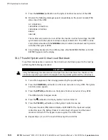
Страница 129: ...backfeed contactors open the battery breaker or disconnect is tripped and the power module is turned off W A R N I N G Power is present inside the UPS cabinet until the upstream input feeder circuit...

Страница 130: ...All power to the critical load is lost when the LOAD OFF is selected in the following step You should use this feature only when you want to de energize the critical load 2 To shut down the UPS press...

Страница 131: ...ergize the critical load NOTE The following instructions are for the Powerware supplied REPO switch If a customer supplied REPO switch is used it may not activate in the same manner refer to the opera...

Страница 132: ...oad is immediately supplied by the bypass source in Bypass mode until the inverters turn on and the UPMs transfer to Normal mode The status indicator on each UPM control panel indicates the UPM is in...

Страница 133: ...nput feeder circuit breakers 2 If the UPMs are dual feed close all UPM Bypass input feeder circuit breakers 3 Observe all UPM control panel displays becoming active indicating logic power 4 Press the...

Страница 134: ...processor remains on and an alarm sounds 3 The UPMs are now operating in Bypass mode and the BYPASS status indicator on each UPM is illuminated The power module PM status indicates READY on each UPM...

Страница 135: ...n UPM NOTE The monitor screen continues to be active until the UPM is isolated from the critical bus W A R N I N G Power is present inside the shutdown UPM cabinet due to connection to the critical bu...

Страница 136: ...utdown To perform maintenance or service on the critical load shut down power to the load by performing the following procedure C A U T I O N Using the following procedure removes all output from the...

Страница 137: ...ritical bus The redundant modules continue to support the critical load The UPM can be shut down only if the remaining UPMs can support the critical load without being overloaded To remove all power f...

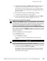
Страница 138: ...remain off until restarted C A U T I O N All power to the critical load is lost when the REPO switch is activated in the following step You should use this feature only when you want to de energize th...

Страница 139: ...ectors or overtemperature alarms The customer interface terminals for external connections are located inside the UPS You should use twisted pair wires for each alarm input and common The building ala...

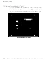
Страница 140: ...a Remote Monitor Panel II RMP II can be installed to monitor the operation of the UPS system from virtually any location within the facility up to 152 4m 500 ft from the UPS The RMP II contains backli...

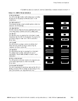
Страница 141: ...wer ON BYPASS The bypass source is supplying the critical load Usually this means that the UPS is not energized The load is not protected in Bypass mode and a horn sounds after 30 seconds UPS ALARM Th...

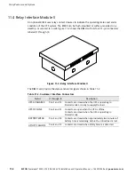
Страница 142: ...Figure 11 2 Relay Interface Module II The RIM II can provide the status and alarm signals shown in Table 11 2 Table 11 2 Customer Interface Connectors Status J1 through J4 Description UPS AVAILABLE Pi...

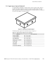
Страница 143: ...be flush mounted or surface mounted on a desktop or secured to a wall Figure 11 3 shows the SCM II Figure 11 3 Supervisory Contact Module II The SCM II provides signals for the indications shown in T...

Страница 144: ...Using Features and Options 11 6 EATON Powerware 9390 UPS 100 160 kVA Installation and Operation Manual S 164201554 Rev E powerware com This page intentionally left blank...

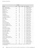
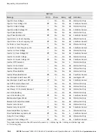
Страница 145: ...ator that an event needing attention is taking place Horn 1 cycles at a one second rate 12 3 System Event Indicators The status indicators on the UPS control panel work in conjunction with the event h...

Страница 146: ...ck Input Switchgear OK Off No 1 HA Condition Cleared Check Inv Temperature Sensor 1 No 1 HA Service Required Check Inv Temperature Sensor OK Off No 1 HA Condition Cleared Check Inverter 1 1 1 HA Servi...

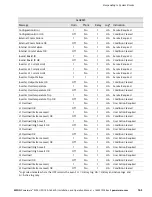
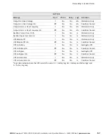
Страница 147: ...vertemperature OK Off No 1 HA Condition Cleared Inverter Overtemperature Trip 1 No 1 HA Service Required Inverter Overtemperature Trip OK Off No 1 HA Condition Cleared L1 Overload 1 No 1 HA User Actio...

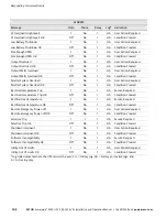
Страница 148: ...Action Required Parallel System Overload OK Off No 1 HA Condition Cleared Rect Overtemperature Trip 1 No 1 HA Service Required Rect Overtemperature Trip OK Off No 1 HA Condition Cleared Rectifier Ove...

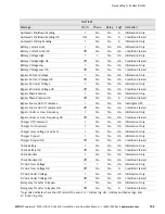
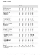
Страница 149: ...on OK Off No No A Condition Cleared Bypass Source Out of Tolerance 1 No No HA Investigate UPS Bypass Source Out of Tolerance OK Off No No HA Condition Cleared Bypass Under or Over Frequency 1 No No HA...

Страница 150: ...Command 1 No No A Information Only Inverter On Command 1 No No HA Information Only Inverter Output Overcurrent 1 No No HA Information Only Inverter Phase Rotation 1 No No HA Information Only Inverter...

Страница 151: ...ondition Cleared Rectifier Current Over 125 1 No No A Information Only Rectifier Input Over Current 1 No No A Information Only UPS Module Off 1 No No A Information Only UPS Module Off OK Off No No A C...

Страница 152: ...o H User Status Inverter Status Off No No No No User Status Inverter Status On No No No No User Status Modem Call Completed Successfully No No No H User Status Modem Connection Established No No No H...

Страница 153: ...erware com COMMAND Message Horn Phone Relay Log Indication Load Off Command Received Yes No No H Information Only To Normal Mode Command No No No H Information Only To Bypass Command No No No H Inform...

Страница 154: ...Responding to System Events 12 10 EATON Powerware 9390 UPS 100 160 kVA Installation and Operation Manual S 164201554 Rev E powerware com This page intentionally left blank...

Страница 155: ...irement of additional network drops This card is provided as standard equipment with the UPS NOTE The Modem Card cannot be installed in X Slot 2 If the UPS has only two X Slots move the ConnectUPS X W...

Страница 156: ...nt UPS or power information With custom views for monitoring status and metering information various user groups can select the most useful view for their specific needs 13 3 Remote Notification For c...

Страница 157: ...rt allows the UPS to call a paging service and send numeric messages Housekeeping The Housekeeping function maintains the link between the UPS and modem 13 4 Terminal Mode NOTE The brackets in the fol...

Страница 158: ...are continually logged through the serial port to the device connected to the port The printed log entries contain a time and date stamp and the alarm text message Terminal mode uses this format for p...

Страница 159: ...Rectifier Under Voltage 03 11 2004 14 27 16 464 ALARM Battery Under Voltage 03 11 2004 14 27 18 954 NOTICE Battery Voltage Low 03 11 2004 14 27 19 169 NOTICE Battery Not Present 03 11 2004 14 27 40 7...

Страница 160: ...Communication 13 6 EATON Powerware 9390 UPS 100 160 kVA Installation and Operation Manual S 164201554 Rev E powerware com This page intentionally left blank...

Страница 161: ...itor bleedoff before attempting internal access to the UPS module W A R N I N G Servicing and maintenance should be performed by qualified service personnel only LETHAL VOLTAGE PRESENT This unit shoul...

Страница 162: ...batteries Released electrolyte is harmful to the skin and eyes and may be toxic A battery can cause electrical shock burn from high short circuit current or fire Observe proper precautions A T T E N T...

Страница 163: ...the doors open b Slide each filter up and remove from the cabinet c Slide the new filters into the brackets until seated on the bottom brackets d Close the doors and secure the latch 3 Record the chec...

Страница 164: ...Maintaining the UPS System 14 4 EATON Powerware 9390 UPS 100 160 kVA Installation and Operation Manual S 164201554 Rev E powerware com This page intentionally left blank...

Страница 165: ...0 Hz Powerware 9390 160 160 160 kVA 50 60 Hz The following sections detail the input output environmental and battery specifications for the UPS 15 2 Single Module Specifications 15 2 1 UPS System Inp...

Страница 166: ...or removal Frequency Regulation 0 01 Hz free running Synchronous to Bypass Bypass within voltage limits of 5 8 of output setting bypass within 0 5 Hz Frequency Slew Rate 1 Hz per second maximum Overlo...

Страница 167: ...5 Module Tie Cabinet Input Operating Input Voltage UPM Dependent 208 Vac for operation from 177 Vac to 229 Vac 220 Vac for operation from 187 Vac to 242 Vac 480 Vac for operation from 408 Vac to 528 V...

Страница 168: ...Product Specifications 15 4 EATON Powerware 9390 UPS 100 160 kVA Installation and Operation Manual S 164201554 Rev E powerware com This page intentionally left blank...

Страница 169: ...sical Features and Requirements 164201554 3 UPS System Oneline Configurations 164201554 4 UPS System Oneline Drawing 164201554 5 Power Wiring Installation Notes 164201554 6 Conduit and Wire Entry Loca...

Страница 170: ...01554 1 1 of 1 TYPICAL POWERWARE 9390 UPS SYSTEM 111504 B DESCRIPTION DATE DRAWING NO SHEET REVISION Installation Information A 2 EATON Powerware 9390 UPS 100 160 kVA Installation and Operation Manual...

Страница 171: ...84 185 Powerware 9390 120 100 480V 480V 467 1030 440 970 6 at 73 162 Powerware 9390 120 120 208V 220V 208V 220V 531 1170 504 1110 6 at 84 185 Powerware 9390 120 120 480V 480V 467 1030 440 970 6 at 73...

Страница 172: ...F Recommended Operating Range 20 25 C 68 77 F Maximum Relative Humidity 95 noncondensing The UPS ventilation requirements are shown in Table C Table C Air Conditioning or Ventilation Requirements Duri...

Страница 173: ...0 Sheet 2 9390 120 100 9390 120 120 9390 160 100 9390 160 120 9390 160 160 208 220 208 220 Single Module Reverse Transfer Single Feed with Typical Maintenance Bypass Panel 480 480 Sheet 3 9390 120 100...

Страница 174: ...TOR K5 OUTPUT CONTACTOR K3 E4 E5 E9 E10 E11 E12 FUSE ALARM RELAY FUSE INTERFACE BOARD BATTERY AUX BATTERY UVR A B C D E1 E2 E3 E6 E7 E8 E12 SEE NOTE 2 AC INPUT TO UPS RECTIFIER AND BYPASS SINGLE FEED...

Страница 175: ...DUAL FEED SINGLE FEED FUSE BACKFEED CONTACTOR K5 OUTPUT CONTACTOR K3 E4 E5 E9 E10 E11 E12 FUSE 3 or 4 WIRE A B C ROTATION ALARM RELAY FUSE INTERFACE BOARD BATTERY AUX BATTERY UVR A B C D E1 E2 E3 E6...

Страница 176: ...PS CRITICAL LOAD DISTRIBUTION UNIT If installing as part of the UPS system a maintenance bypass without a rectifier input breaker a minimum of two separate feeds with upstream feeder breakers or one f...

Страница 177: ...YPICAL PARALLEL SYSTEM 1 1 AND 2 0 CONFIGURATIONS C C 164201554 4 G NOTE 1 UPM and system bypass input feeds must come from the same source 2 Remove jumper for dual feed 3 See Note 27 on page A 21 for...

Страница 178: ...K3 FUSE BATTERY CONVERTER RECTIFIER INVERTER K1 UPM 2 E1 E2 E3 E6E 7E8 E12 A B SEE NOTE 2 D BATTERY CABINET BATTERY BREAKER E4 E5 E9 E10 E11 E12 FUSE K5 STATIC SWITCH FUSE K3 FUSE BATTERY CONVERTER RE...

Страница 179: ...D BATTERY CABINET BATTERY BREAKER E4 E5 E9 E10 E11 E12 FUSE K5 STATIC SWITCH FUSE K3 FUSE BATTERY CONVERTER RECTIFIER INVERTER K1 UPM 4 E1 E2 E3 E6E 7E8 E12 A B SEE NOTE 2 D BATTERY CABINET BATTERY BR...

Страница 180: ...Load Full Load Current 3 Phases 1 Neutral if required 1 Ground D Amps 278 262 120 Minimum Conductor Size Number per Phase AWG or kcmil each 3 0 2 4 0 1 Neutral Bonding Jumper Minimum Conductor Size N...

Страница 181: ...ber per Phase AWG or kcmil each 4 0 2 4 0 1 Neutral Bonding Jumper Minimum Conductor Size Number See Note 7 AWG or kcmil each 1 0 1 2 1 NOTE Callout letters A B C and D map to Drawing 164201554 4 shee...

Страница 182: ...AC Output to Critical Load Full Load Current 3 Phases 1 Neutral if required 1 Ground D Amps 444 420 192 Minimum Conductor Size Number per Phase AWG or kcmil each 400 2 1 0 2 Neutral Bonding Jumper Mi...

Страница 183: ...ex E3 Phase C 2 2 0 500 kcmil 31 1 275 4 mm Hex AC Input to UPS Rectifier Dual Input E1 Phase A 2 2 0 500 kcmil 31 1 275 4 mm Hex E2 Phase B 2 2 0 500 kcmil 31 1 275 4 mm Hex E3 Phase C 2 2 0 500 kcmi...

Страница 184: ...2 6 250 42 4 375 5 16 in Hex E2 Phase B 2 6 250 42 4 375 5 16 in Hex E3 Phase C 2 6 250 42 4 375 5 16 in Hex AC Input To Bypass Dual Input E6 Phase A 2 6 250 42 4 375 5 16 in Hex E7 Phase B 2 6 250 4...

Страница 185: ...sizes were chosen from NEC Table C1 type letters RHH RHW RHW 2 TW THW THHW THW 2 Table J Power Cable Conduit Requirements UPS Model Voltage Terminal Number of Wires in Conduit Minimum Conduit Trade Si...

Страница 186: ...Cont d UPS Model Voltage Terminal Number of Wires in Conduit Minimum Conduit Trade Size inches Number of Conduits Powerware 9390 160 160 208 220 AC AC Input to UPS A B C Gnd 4 3 1 2 2 AC Input to Byp...

Страница 187: ...rovided with maximum input circuit breaker current ratings from Table K in accordance with the National Electrical code ANSI NFPA 70 16 Source protection for the AC input to bypass should be treated a...

Страница 188: ...l DC input overcurrent protection and disconnect switch for the remote battery location is to be provided by the user Table M lists the maximum rating for continuous duty rated circuit breakers satisf...

Страница 189: ...ding jumper installed in accordance with Note 7 on page A 13 DO NOT install both a source neutral and a bonding jumper See Table O through Table Q for system neutral bonding jumper wire sizes Bonding...

Страница 190: ...priate information in Table N 31 For parallel system ratings see the appropriate information in Table O through Table Q Table N Recommended UPM Output MOB Main Output MIS and Bypass MBP Circuit Breake...

Страница 191: ...l Bonding Jumper Minimum Conductor Size Number See Note 27 AWG or kcmil each 1 0 1 4 1 2 0 and 2 1 AC Input to Tie Cabinet Bypass optional Full Load Current 3 Phases 1 Neutral if required 1 Ground F A...

Страница 192: ...al Bonding Jumper Minimum Conductor Size Number See Note 27 AWG or kcmil each 1 0 1 4 1 2 0 and 2 1 AC Input to Tie Cabinet Bypass optional Full Load Current 3 Phases 1 Neutral if required 1 Ground F...

Страница 193: ...al Bonding Jumper Number See Note 27 AWG or kcmil each 2 0 1 2 1 2 0 and 2 1 AC Input to Tie Cabinet Bypass optional Full Load Current 3 Phases 1 Neutral if required 1 Ground F Amps 888 840 384 AC Out...

Страница 194: ...4201554 Rev E powerware com 32 Required parallel system wiring length must be in accordance with the following formula as referenced to the diagram below to ensure approximately equal current sharing...

Страница 195: ...R PUNCH CONDUIT HOLES DESCRIPTION DATE DRAWING NO SHEET REVISION BOTTOM ENTRY CONDUIT LANDING FOR AC INPUT AND OUTPUT DC INPUT DC CONTROL AND INTERFACE CONNECTIONS REMOVE PANEL TO DRILL OR PUNCH CONDU...

Страница 196: ...TO ROUTE WIRES BETWEEN CABINETS INSTALL NYLON GROMMET AFTER REMOVAL OF KNOCKOUTS INSIDE PANELS INTER CABINET WIRING ACCESS KNOCKOUTS REMOVE KNOCKOUTS AS REQUIRED TO ROUTE WIRES BETWEEN CABINETS INSTA...

Страница 197: ...GROUND TERMINALS AC INPUT TO UPS RECTIFIER AND BYPASS A B C N DESCRIPTION DATE DRAWING NO SHEET REVISION DC INPUT FROM BATTERY TO UPS AND AC OUTPUT TO CRITICAL LOAD A B C N WIREWAY FOR TOP ENTRY POWE...

Страница 198: ...INPUT FROM BATTERY E4 E5 AC INPUT TO UPS BYPASS DUAL INPUT AC INPUT TO UPS RECTIFIER AND BYPASS SINGLE INPUT AC INPUT TO UPS RECTIFIER DUAL INPUT PHASE A E6 PHASE B E7 PHASE C E8 PHASE A E9 PHASE B E1...

Страница 199: ...ust be removed or opened to gain access to terminals DESCRIPTION DATE DRAWING NO SHEET REVISION AC INPUT TO UPS RECTIFIER AND BYPASS A B C N DC INPUT FROM BATTERY TO UPS AND AC OUTPUT TO CRITICAL LOAD...

Страница 200: ...PHASE A E1 PHASE B E2 PHASE C E3 PHASE A E6 PHASE B E7 PHASE C E8 NEUTRAL TERMINALS E12 RECTIFIER INPUT TERMINALS BYPASS INPUT TERMINALS OUTPUT TERMINALS SINGLE FEED JUMPER BUS AC INPUT TO UPS BYPASS...

Страница 201: ...e with X Slot connectivity cards must be provided by facility planners or the customer Table R TB1 and TB2 Interface Connections Terminal TB1 Name Description 1 Remote EPO NC Input Normally closed dry...

Страница 202: ...NTRY INTERFACE WIRING NOTE Metal shields covering wiring terminals must be removed or opened to gain access to terminals 1 2 3 4 INTERFACE TERMINAL LOCATIONS OPTIONAL X SLOT COMMUNICATION BAY OPTIONAL...

Страница 203: ...the normally closed EPO contact is not used 032406 D 164201554 8 DESCRIPTION DATE DRAWING NO SHEET REVISION INTERFACE WIRING INSTALLATION NOTES AND TERMINAL LOCATIONS INTERFACE TERMINALS BUILDING ALAR...

Страница 204: ...for use with either normally open or normally closed contacts All control wiring and relay and switch contacts are customer supplied 2 The building alarms can be programmed to display the alarm functi...

Страница 205: ...l wiring from the UPS must be connected to the DC source disconnect device 10 Battery Aux and UVR wiring should be a minimum of 18 AWG Table S Battery Disconnect Interface BATTERY AUX BATTERY BREAKER...

Страница 206: ...es to the UPS The REPO switch must be a latching type switch with a dedicated circuit 12 A jumper wire must be connected between pins 1 and 2 on TB1 if a normally closed EPO switch is not used or a no...

Страница 207: ...ypass auxiliary contacts as applicable See Table V Table V Typical Maintenance Bypass Panel Auxiliary Contact Control Wiring TB1 9 10 MAINTENANCE BYPASS PANEL PROVIDED BY OTHERS UPS NOTE REFER TO THE...

Страница 208: ...ritical bus by facility planners or the customer See Table W Table W Typical Maintenance Bypass Panel Key Switch Control Wiring Neutral Key Switch Lamp 120 VAC Fused TB2 Output Contactor K3 9 10 Solen...

Страница 209: ...ng Install the interface wiring in separate conduit from the power wiring 17 Use Class 1 wiring methods as defined by the NEC for parallel interface wiring The wire should be shielded twisted pair rat...

Страница 210: ...HAIN PARALLEL SYSTEM CAN WIRING TWISTED PAIR TWISTED PAIR TWISTED PAIR UPM 1 CAN CARD J3 UPM 2 CAN CARD J3 UPM 3 CAN CARD J3 IF INSTALLED UPM 4 CAN CARD J3 IF INSTALLED 10 of 13 Installation Informati...

Страница 211: ...erminations All UPMs From To TB2 1 Bldg Alarm 2 TB2 3 On Byp NO TB2 2 Bldg Alarm 2 Return TB2 4 Byp Common 032406 E 164201554 8 DESCRIPTION DATE DRAWING NO SHEET REVISION INTERFACE WIRING INSTALLATION...

Страница 212: ...AND RELAY INTERFACE MODULE TERMINAL LOCATIONS TERMINAL TB 3 120 VAC POWER SUPERVISORY CONTACT MODULE TERMINAL LOCATIONS GROUND TERMINAL TERMINAL TB 1 SIGNAL CONNECTIONS FROM THE UPS TERMINAL TB 3 120...

Страница 213: ...imum distance between the UPS cabinet and RMP II RIM II or SCM II is not to exceed 500 feet 22 Use Class 1 wiring methods as defined by the NEC for RMP II RIM II or SCM II power and signal wiring Powe...

Страница 214: ...554 9 FRONT VIEW RIGHT SIDE VIEW DESCRIPTION DATE DRAWING NO SHEET REVISION Dimensions are in millimeters inches Installation Information A 46 EATON Powerware 9390 UPS 100 160 kVA Installation and Ope...

Страница 215: ...9 TOP VIEW BOTTOM VIEW Dimensions are in millimeters inches 2 of 4 DESCRIPTION DATE DRAWING NO SHEET REVISION Installation Information A 47 EATON Powerware 9390 UPS 100 160 kVA Installation and Operat...

Страница 216: ...ITH OPTIONAL FLOOR MOUNTING BRACKETS Dimensions are in millimeters inches 3 of 4 DESCRIPTION DATE DRAWING NO SHEET REVISION Installation Information A 48 EATON Powerware 9390 UPS 100 160 kVA Installat...

Страница 217: ...SEISMIC MOUNTING BRACKETS Dimensions are in millimeters inches 4 of 4 DESCRIPTION DATE DRAWING NO SHEET REVISION SEISMIC KIT INSTALLATION Installation Information A 49 EATON Powerware 9390 UPS 100 160...

Страница 218: ...QUIPMENT Dimensions are in millimeters inches NOTE 1 Conduit and wiring between the Remote Emergency Power off REPO and the UPS to be supplied by the customer 2 Maximum distance between the Remote EPO...

Страница 219: ...SURFACES FLUSH MOUNT USE 10 PAN HEAD SCREWS MOUNT WITH VENT HOLES FACING UP SURFACE MOUNT USE 10 PAN HEAD SCREWS FOR HANGING MOUNT WITH VENT HOLES FACING UP Dimensions are in millimeters inches Insta...

Страница 220: ...E SURFACES FLUSH MOUNT USE 10 PAN HEAD SCREWS MOUNT WITH VENT HOLES FACING UP SURFACE MOUNT USE 10 PAN HEAD SCREWS FOR HANGING MOUNT WITH VENT HOLES FACING UP Dimensions are in millimeters inches Inst...

Страница 221: ...E 111504 B DESCRIPTION DATE DRAWING NO SHEET REVISION 164201554 12 2 of 2 15 PIN D SUB CONNECTORS Installation Information A 53 EATON Powerware 9390 UPS 100 160 kVA Installation and Operation Manual S...

Страница 222: ...IVE SURFACES FLUSH MOUNT USE 10 PAN HEAD SCREWS MOUNT WITH VENT HOLES FACING UP SURFACE MOUNT USE 10 PAN HEAD SCREWS FOR HANGING MOUNT WITH VENT HOLES FACING UP Dimensions are in millimeters inches In...

Страница 223: ...f the Product b if the Product is moved to a new location by someone other than an authorized Eaton Customer Service Engineer in the USA or Agent outside of the USA or c if the Product s serial number...

Страница 224: ...Warranty W 2 EATON Powerware 9390 UPS 100 160 kVA Installation and Operation Manual S 164201554 Rev E powerware com This page intentionally left blank...

Страница 225: ......

Страница 226: ...164201554E 164201554 E...

Отзывы: