


1
Issue: 04
Part Number: 31508414
Date: 2019-06-28
UPS5000-A-200 kVA
Quick Guide
1
1
Overview
Copyright © Huawei Technologies Co., Ltd. 2019. All rights reserved.
1
Overview
UPS Model
Capacity
Weight
Dimensions (H x W x D)
UPS5000-A-200K-ST
200 kVA
370 kg
2000 mm x 600 mm x 850 mm
UPS5000-A-200K-FT
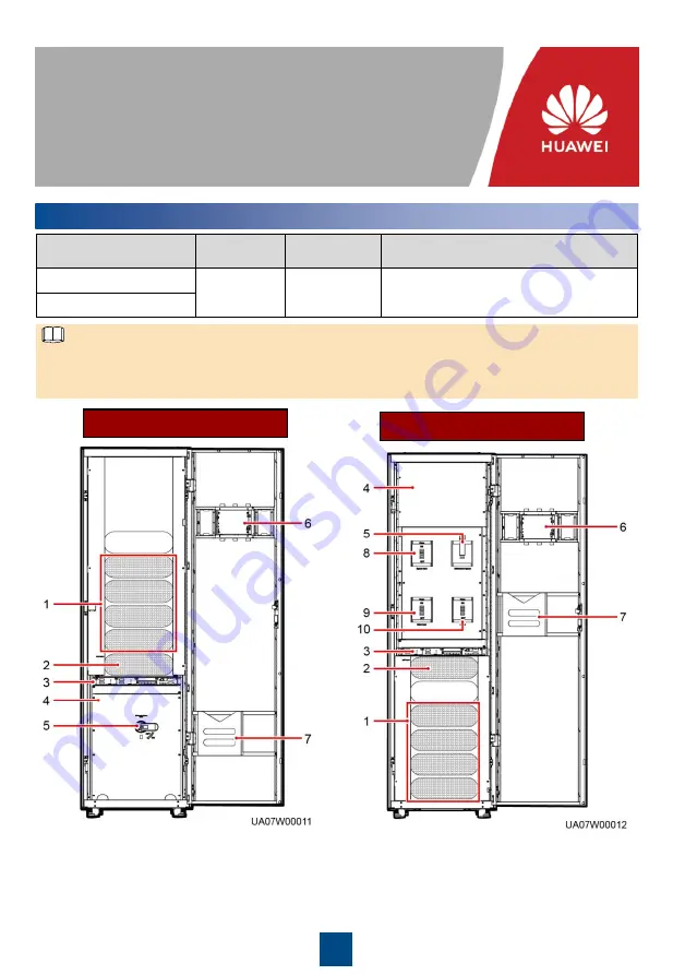
UPS5000-A-200K-ST
UPS5000-A-200K-FT
(1) Power units
(2) Bypass unit
(3) Control unit
(4) Power distribution
subrack cover
(5) Maintenance bypass switch
(6) Monitor display unit (MDU)
(7) Folder
(8) Bypass input switch
(9) Main input switch
(10) Output switch
The UPS5000-A-200K-ST is a standard configuration model. The UPS5000-A-200K-FT is a full
configuration model. A UPS in standard configuration has no mains input switch, bypass input
switch, or output switch.
NOTE


