October 2016
Instruction Book
IB019008EN
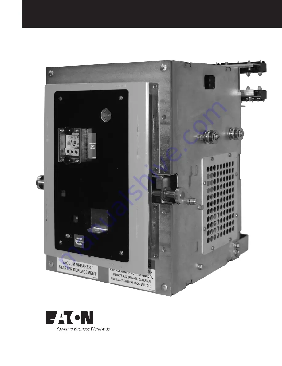
FP-25-LV-VSR
Breaker-To-Motor Starter Conversion
Effective
FP-25-LV-VSR 425A Shown
Страница 1: ...October 2016 Instruction Book IB019008EN FP 25 LV VSR Breaker To Motor Starter Conversion Effective FP 25 LV VSR 425A Shown...
Страница 2: ...quipment do not purport to be covered by these instructions If further information is desired by purchaser regarding his particular installation operation or maintenance of particular equipment contac...
Страница 3: ...PECTION 13 5 1 CELL MODIFICATION INSTRUCTIONS 13 5 2 EXAMINATION FOR DAMAGE 14 5 3 ELECTRONIC OVERLOAD RELAY C440 15 5 4 INSERTION PROCEDURE 16 5 5 REMOVAL PROCEDURE 18 5 6 MANUAL OPERATIONAL CHECK 18...
Страница 4: ...ss 10 and 20 trip characteristics and Manual or Manual Automatic Reset An electro mechanical overload relay Eaton type C306 may be substituted for the electronic overload relay This relay is equipped...
Страница 5: ...n com FP 25 LV VSR Breaker To Motor Starter Conversion Table 2 FP 25 LV VSR Dimensions Device Type Existing Breaker Rated Continuous Current at 60 Hz Amps A B C D E F G H FP 25 LV VSR 425A 5 55 4 00 8...
Страница 6: ...R from the enclosure before performing any maintenance Failure to do so could result in electrical shock leading to death severe personnel injury or property damage Do not work on a LV VSR with the se...
Страница 7: ...for shipping damage it is best to return it to its original shipping crate until it is ready to be installed in the Metal Enclosed Switchgear When a LV VSR is ready for installation a lifting harness...
Страница 8: ...sion 2 1 5 9 10 8 3 7 4 6 Figure 3 2 Front External View of FP 25 LV VSR Front External View 1 Trip Button 5 Crank Access Shutter 9 Guide Roller 2 Overload Relay Access 6 Lock Out Lock Tag 10 Racking...
Страница 9: ...P 25 LV VSR Breaker To Motor Starter Conversion Figure 3 3 Rear External View of FP 25 LV VSR Front External View 1 Secondary Contacts 3 Primary Disconnects 5 Lifting Point 2 Overload Relay Current Tr...
Страница 10: ...1005 8 m the contactor is designed to tolerate normal variations in barometric pressure If the contactor is to be operated over 3 300 ft 1005 8 m above sea level consult the factory Contact Wear Allo...
Страница 11: ...he LV VSR is being levered between the TEST and CONNECT positions Consequently it prevents the LV VSR from closing automatically even though the control close contact may have been made while the LV V...
Страница 12: ...self aligning See Insertion Procedure line contact slip type connectors The multiple finger arrangement on the LV VSR makes contact with a stationary mounted element The contact surfaces on the stati...
Страница 13: ...T INTERCHANGEABLE WITH CIRCUIT BREAKER EY ARE SUPPLIED WITH CELL CODE REJECTION PLATES DO NOT ATTEMPT TO MODIFY OR REMOVE THE NEW CELL CODE REJECTION PLATES MODIFICATIONS OR OMISSIONS OF THE CELL CODE...
Страница 14: ...and open normally 17 Perform an AC hipot test per section 6 prior to insertion into the switchgear 18 Check the V201 contactor per section 6 3 2 of this manual prior to insertion Figure 5 6 Rejection...
Страница 15: ...5 10 or 5 11 C440 relay features include a push pull button for trip and test a push button for reset and the full load current dial Adjacent to the FLA dial the C440 electronic overload relay has dip...
Страница 16: ...re 5 13 provides hot motor time current information for the C440 Figure 5 13 Average Hot Trip Curve for Three Phase Motors Figure 5 14 Operating Modes for C440 9 Eaton Instructional Leaflet IL04210001...
Страница 17: ...r and insert the crank turn the crank clockwise until the position indicator on the starter shows CONNECT position Figure 5 18 9 Remove the racking crank the shutter will automatically be returned The...
Страница 18: ...ECTRICAL OPERATIONAL CHECKS WARNING DO NOT PERFORM ELECTRICAL OPERATION CHECKS WITH THE LV VSR IN THE CONNECT POSITION BECAUSE OF THE POSSIBILITY OF CONNECTING DE ENERGIZED LOAD CIRCUITS TO THE ELECTR...
Страница 19: ...O NOT PERFORM ANY MAINTENANCE WITH THE LV VSR IN THE SWITCHGEAR 6 3 2 Contact Wear Allowance Contact material vaporizes from the contact faces during every interruption and condenses inside the bottle...
Страница 20: ...ul withstand indicates that all interrupters have satisfactory vacuum levels If there is a breakdown the contactor should be replaced before placing the LV VSR in service 7 After the high potential is...
Страница 21: ...is essential for maintaining the reliable performance of the mechanism The LV VSR should be re lubricated once a year The locations shown in Figure 30 should be lubricated with a drop of non syntheti...
Страница 22: ...r of the auxiliary contact plungers should bottom solidly in the closed contactor position as discussed under Magnet Operating Range If required the auxiliaries can be adjusted by resetting their moun...
Страница 23: ...general order number from the nameplate 2 Describe the item give the style number and specify the quantity required 3 Specify the voltage for electrical components 4 Specify the method of shipping des...
Страница 24: ...evard Cleveland OH 44122 United States Eaton com 2016 Eaton All Rights Reserved Printed in USA Publication No IB019008EN October 2016 Eaton is a registered trademark All trademarks are property of the...