


LCD Interface Operation
Eaton ePDU G3 Operation Manual P-164000277—Rev 5
59
6.
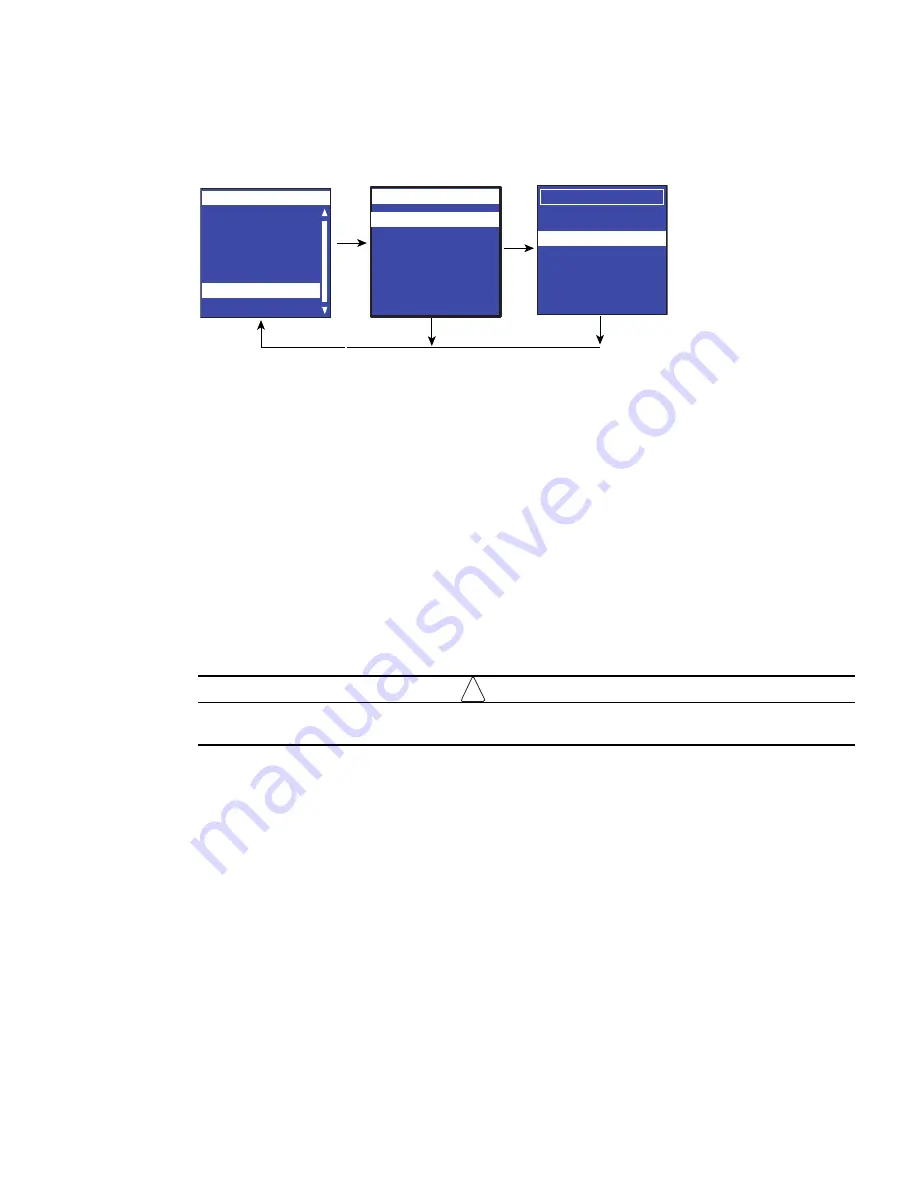
Select Load Config then click
OK
to start loading the ConfigurationData.xml file into the eNMC module
(see Figure 63).
Figure 63. Example Load Config.
7.
When the file is successfully loaded, click
OK
in response to the confirmation message.
8.
Click
OK
to start loading the ConfigurationPdu.xml file into the eNMC module.
9.
When the file is successfully loaded, click
OK
in response to the confirmation message.
10. Remove the USB drive and select
Exit
from the USB Flash Mode menu.
Save the ePDU Hardware Configuration File to the USB
See “Replacing the ePDU Network Management and Control Module” on page 117 to understand this
selection in proper context. This procedure is used as part of the eNMC module replacement procedure. Each
ePDU model has a model-specific hardware configuration file for its eNMC module that can only be used on
the specified model. This procedure allows you to copy the ePDU hardware configuration file from a working
ePDU of the same model and store it on a USB flash drive so that it can be uploaded to a new eNMC module.
To save the ePDU model-specific hardware configuration file to a USB drive:
1.
Make sure the eNMC module is powered ON. Connect a USB flash drive to a working ePDU.
!
IMPORTANT
This ePDU must be of the same model type and configuration as the ePDU that houses the eNMC
you will replace.
2.
When the LCD interface pop-up confirms that the USB flash drive is detected, click
OK
, and press
Enter
to return to the Main Menu. (If not confirmed within 10 seconds, the pop-up goes away by itself.)
3.
From the LCD Settings menu, select USB Flash Mode. Press
Enter
, select
yes
to confirm, and then press
Enter
again. The module restarts. (If there is no action within one minute, the eNMC module exits USB
Flash Mode. Remove and reinsert the flash drive to access this menu again.)
4.
Select Save eNMC file to save the ePDU hardware configuration file to the USB drive (see Figure 64). The
file will save to the eNMC/config/hw path at the USB drive root directory (see Figure 65).).
Daisy Chain
Settings
LCD
IPv4
Factory
Display
Language
ESC
Enter
Main Menu
Active Alarms
Alarms History
Meters
Control
ePDU Info
Main Menu
Settings
Enter
ESC
USB Flash Mode
Main Menu
.
Upgrade F/W
Save eNMC file
Load eNMC file
Exit
USB Flash Mode
Save Config
.
Load Config


