


Maintenance and Alarms
Eaton ePDU G3 Operation Manual P-164000277—Rev 5
118
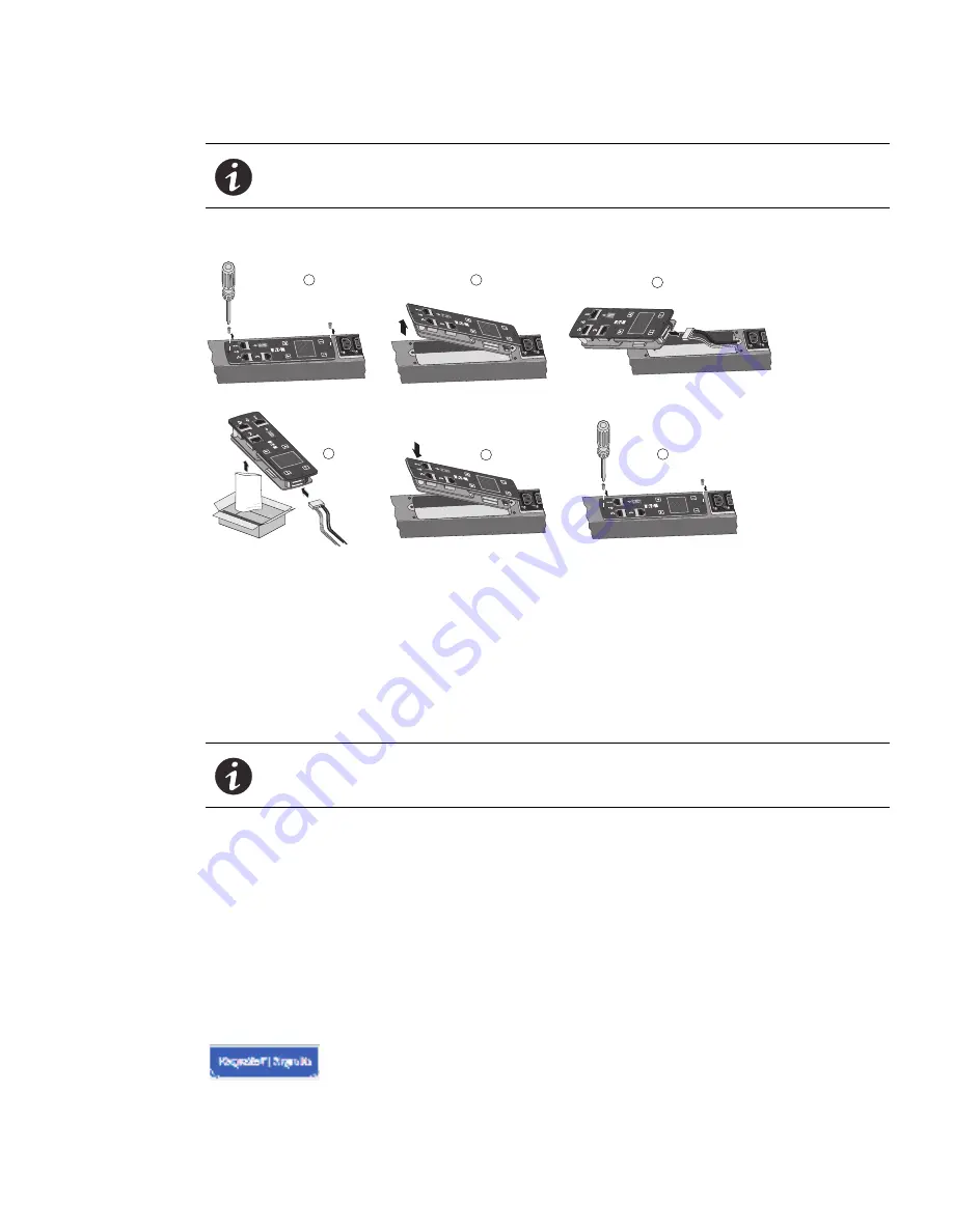
To replace the eNMC module (see Figure 85):
Figure 85. Replacement Procedure
1.
Remove the two eNMC module mounting screws.
2.
Tilt up one side of the eNMC module and locate the attached cable harness.
3.
Disconnect the cable harness and remove the eNMC module.
4.
Locate and unwrap the new eNMC module. Connect the cable harness to the new eNMC module.
5.
Reinsert the new eNMC module.
6.
Install the two eNMC module mounting screws.
7.
The new eNMC module will not have the same MAC address as the one you are replacing. Ensure the old
MAC address label is discarded and that new MAC address label is firmly adhered to the product.
8.
Download the ePDU model’s hardware configuration file using one of the following processes:
l
From the Web (go to Step 9)
l
To the USB with an ePDU with the same configuration (go to Step 15)
9.
Go to www.eaton.com/ePDU.
10. If available, click the Sign In button in the upper left corner of the page to sign in (see Figure 86). Return to
the ePDU home page. (The Sign In button will not be available if you are already logged in. The button
selection will be “Sign Out” instead of “Sign In.”)
Figure 86. Sign In/Sign Out Button
NOTE
See “USB Flash Mode Submenu” on page 57 for more information about saving
and uploading the user configuration files that store the settings customized by the
user, such as the network parameters, outlet names, and threshold values
NOTE
After the new eNMC module is connected, the “internal communication error”
message displays until the configuration file is uploaded to the eNMC module.
1
2
3
4
5
6


