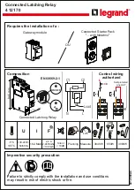
4
Instruction Booklet
IB0191002EN
Effective November 2019
EAFR-101C arc point sensor relay
user manual
EATON
www.eaton.com
3 Operation and configuration
3.1 LED indicator functions
The EAFR-101C contains 16 indication LEDs . A user definable text
pocket can be slid in under the label for identifying each LED func-
tion (except POWER and ERROR LEDs) . LEDs are located at the
front plate of the relay for clear viewing without a need for opening
doors .
During power up, the relay performs an LED test . All LEDs are
turned on for two seconds and then off . Only the blue POWER LED
will remain on . After powered up, the relay goes into protection
mode in 50 ms even while the LED test is being performed .
During normal operation, the blue power LED is ON, as are any CB
open/close status LED’s for connected CB’s .
The sensor LEDs are off during the inactive condition . If a point arc
sensor is activated, the corresponding sensor channel LED will turn
on if the activation is longer than 1 .5 ms . The sensor LED activation
function is latched (steady light) . To clear the LED, the “SET” button
should be pressed .
In case of a loose sensor wire and binary input wires or configura-
tion mismatch (new sensor attached without running auto-configu-
ration system setup (see Section 3 .3 .1) situation, the corresponding
LED for that sensor will start flashing and the ERROR LED will
activate .
The Binary I/O LEDs indicate the I/O-line status . If any of the lines
become active for more than 1 .5 ms, the corresponding LED will
turn on (latch) .
In a trip situation, the corresponding trip LED will turn on . Trip
outputs are controlled by the dipswitch settings (see Section 3 .5) .
All activation and trip indication LEDs are latched, even if the
dipswitch setting is in the non-latched mode . They have to be
cleared by pushing the “SET” button .
LED indications are stored in non-volatile EPROM memory for iden-
tifying the trip information in case the auxiliary power is lost . When
re-powering the relay after power supply loss, the actual LED status
can be visualized from the front of the relay .
3.2 LED operation quick guide
Table 1. LED operation quick guide.
LED
Off
Steady On
Blinking
Action if Abnormal
POWER - Blue
Auxiliary supply
disconnected.
Auxiliary power connected.
N/A
Check the power source.
ERROR - Red
System healthy.
System failure.
Configuration mismatch.
Protection partly operational.
Verify system condition. See Sections
11: Troubleshooting guide and 5: System
self-supervision.
T1, and T3 - Red
Normal status.
Trip relays T1 and T3 activated.
N/A
Check the reason for trip. Clear the fault
and reset indications by pushing SET
button.
T2, and T3 - Red
Normal status.
Trip relays T2 and T3 activated.
N/A
Check the reason for trip. Clear the fault
and reset indications by pushing SET
button.
BI1 - Amber
CB open.
CB closed.
Loose connection/dipswitch
mismatch.
Check the binary input wiring/dipswitch
setting.
BI2 - Amber
CB closed.
CB open.
Loose connection/dipswitch
mismatch.
Check the binary input wiring/dipswitch
setting.
BI3 - Amber
CB open.
CB cLosed.
Loose connection/dipswitch
mismatch.
Check the binary input wiring/dipswitch
setting.
BI4 - Amber
CB closed.
CB open.
Loose connection/dipswitch
mismatch.
Check the binary input wiring/dipswitch
setting.
BI5 - Amber
Normal status.
Current/MT indication.
Binary input 5 has loose
connection.
Check the binary input wiring.
BI6 - Amber
Normal status.
Blocking signal input..
Binary input 6 has loose
connection.
Check the binary input wiring.
BO1 - Amber
Normal status.
Light > output.
N/A
N/A
BO2 - Amber
Normal status.
Blocking signal high.
N/A
N/A
S1 - Amber
Normal status.
Sensor channel 1 activated by
light information
Sensor channel 1 has loose
connection or the system set-
up was not performed. Also
activated by pressure information
(if L+P sensors used).
Check why the sensor activated, check
the sensor wire connection, or perform
the system set-up (see Section 3.3.1:
Auto-configuration (System setup).
S2 - Amber
Normal status.
Sensor channel 2 activated by
light information.
Sensor channel 2 has loose
connection or system set-up
not performed. Also activated
by pressure information (if L+P
sensors used).
Check why the sensor activated, check
the sensor wire connection, or perform
system set-up (see Section 3.3.1: Auto-
configuration (System setup).
S3 - Amber
Normal status.
Sensor channel 3 activated by
light information.
Sensor channel 3 has loose
connection or system set-up
not performed. Also activated
by pressure information (if L+P
sensors used).
Check why the sensor activated, check
the sensor wire connection, or perform
system set-up (see Section 3.3.1: Auto-
configuration (System setup).
S4 - Amber
Normal status.
Sensor channel 4 activated by
light information
Sensor channel 4 has loose
connection or system set-up
not performed. Also activated
by pressure information (if L+P
sensors used).
Check why the sensor activated, check
the sensor wire connection, or perform
system set-up (see Section 3.3.1: Auto-
configuration (System setup).