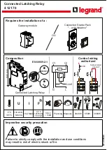


Connected Latching Relay
4 121 70
LE12069AC
Composition
EN 60669-2-1
Requires the installation of a :
Connected Starter Pack
"... with Netatmo"
Gateway module
OU
84.5 mm
17.8 mm
ON/OFF
Control wiring
authorized
Connected Latching Relay
F
16A MAX
2,4 à
2,4835Ghz
<100 mW
-5°C
+45°C
100-240V~
50/60Hz
U
I
650W
3000W
3840W
LED
FLUO
1
2
3
4
5
6
7
8
9
10
11
12
13
14
15
16
17
18
19
20
21
22
23
24
25
26
27
28
29
30
oooooooooooooooo
oooooooooooooooo
ooooooooooo
oooooooooooooo
ooooooooooo
ooooooooooooooo
oooooooo
ooooooooooooo
oooooo
oooooooooooooo
ooooooooooo
oooooooooooooooo
oooooooooooooo
ooooooooooo
oooooooooooooo
oooooooooooo
ooooooooooooooo
oooooooooooooo
ooooooooooo
oooooooooooooooo
oooooooooooooo
ooooooooooo
oooooooooooooo
oooooooooooooooo
ooooooooooo
oooooooooooooooo
oooooooooooooo
ooooooooooo
oooooooooooooo
oooooooooooo
1
2
3
4
5
6
7
8
9
10
11
12
13
14
15
16
17
18
19
20
21
22
23
24
25
26
27
28
29
30
1
oooooooooooooooo
oooooooooooooooo
ooooooooooo
oooooooooooooo
ooooooooooo
ooooooooooooooo
1
2
3
4
5
6
7
11
12
13
14
15
16
17
18
19
20
21
22
23
24
25
26
27
28
29
30
10
9
8
Jan
Feb
Mar
Planning Measure
kWh
< 10dB
L
N
Load
C1
C2
Silent
L
Self-protected
Line OUT
C1
C2
C1
C2
MCB
Failure to strictly comply with the installation and use conditions
may result in risk of electric shock or fire.
Imperative security precaution


