BISTABLE RELAY PBM-02
INSTRUCTION MANUAL
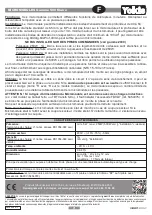
APPEARANCE
ver. 0.4.2 _ 2006.06.26_08:00
FEATURES
TECHNICAL PARAMETERS
DESCRIPTION
PBM - 02
Input (supply) terminals : L, N
Input rated voltage: 230 V~
Input voltage tolerance: from -15 to +10 %
Nominal frequency: 50 / 60 Hz
Rated power consumption: 24 mA
Supply voltage control indicator: LED green
Release terminals: IN, IN, IN
Release control current: 930 µA
Central control terminals: Set, Reset
Power/relay supply indicator: LED red
Relay operating indicator: TEST button
Output relay parameters: 1NO - 16 A / 250 V AC1 4000 VA
Number of terminal clamps: 10
Section of connecting cables: from 0,2 to 2,50 mm
2
Ambient temperature range: from -20 to +45
o
C
Operating position: free
Mounting: TH35 rail (PN-EN 60715)
Protection degree: IP20 (PN-EN 60529)
Protection class: II
Overvoltage category: II
Pollution degree: 2
Rated impulse withstand voltage: 1 kV (PN-EN 61000-4-5)
Dimensions (height / width / depth): monomodular (17,5 mm) 90x17,5x66 mm
Weight: 80 g
Reference standards: PN-EN 60669-1; PN-EN 60669-2-1
PN-EN 61000-4-2,3,4,5,6,11
The bistable relay PBM-02 is used to
control lighting or other devices by means
of monomodular pushbuttons connected
in a parallel way. Pushing any button cau-
ses switching on or switching off the de-
vices connected to output terminals. The
controlling impulse can be L or N line sig-
nal. The Set and Rest control inputs allow
central control of a relay group. Using the
inner relay memory allows to remember
its current mode in cases of power supply
loss.
Zakład Mechaniki i Elektroniki
ZAMEL
sp.j.
J.W. Dzida, K. Łodzińska
ul. Zielona 27, 43-200 Pszczyna, Poland
Tel. +48 (32) 210 46 65, Fax +48 (32) 210 80 04
www.zamel.pl,
e-mail:
The device is desig-
ned for one-phase in-
stallation and must be
installed in accordance
with standards valid in
a particular country.
The device should be
connected according to the details inclu-
ded in this operating manual. Installation,
connection and control should be carried
out by a qualified electrician staff, who act
in accordance with the service manual
and the device functions. Disassembling
of the device is equal with a loss of gua-
rantee and can cause electric shock. Be-
fore installation make sure the connec-
tion cables are not under voltage. The
cruciform head screwdriver 3,5 mm sho-
uld be used to instal the device.Improper
transport, storage, and use of the device
influence its wrong functioning. It is not
advisable to instal the device in the follo-
wing cases: if any device part is missing
or the device is damaged or deformed. In
case of improper functioning of the devi-
ce contact the producer.
CAUTION
ی Bistable lighting control,
ی input rated indicator – LED green,
ی relay mode indicator – LED red,
ی central control function,
ی relay mode memory,
ی system releasing from the L or N
cable,
ی cooperation with monostable pus
-
hbuttons equipped with illumination
lamps,
ی TEST function,
ی double-wire controll installation,
ی voltage relay output - one NO (norma
closed) contact max 16 A capacity.
Output (load) relay
Supply voltage control indicator
Input supply terminals (L)
Input supply terminals (N)
Relay test
Power/relay supply indicator
Central control terminals (S, R)
Release terminals
(IN, IN, IN)
terminals (11, 11, 14)