


22
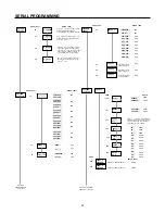
SERIAL PROGRAMMING
COUNT IN
PROGRAM
Next item is
PROGRAM INPUTS
in right column
PROGRAM
SCALERS
R DEC PT
- - - - -
.
- - - - - -
.
C DEC PT
C SCALER
R SCALER
READ (RPI)
00
01
02
WRITE (WPI)
00nnnnnn nnnnnn is a decimal number
between 000001 and 999999. If
nnnnnn=000000, then 1.00000 is loaded.
01d where d is between 0 and 5. The
decimal point will be placed to the right
of the 10 digit.
d
02dnnnnn Where d is between 0 and 5.
The decimal point will be placed to the
right of the 10 digit. nnnnn is a decimal
number between 00001 and 99999. If
nnnnn=00000, then 1.0000 is loaded.
03d Where d is between 0 and 5. The
decimal point will be placed to the right
of the 10 digit.
d
03
CONTACT
ADD/SUB
CONTACT
ADD/ADD
SOLID ST
Cx1/DIR
SOLID ST
Cx2/DIR
SOLID ST
QUAD x2
SOLID ST
ADD/SUB
CONTACT
C/DIR
SOLID ST
QUAD x1
SOLID ST
ADD/ADD
READ (RPI)
10
WRITE (WPI)
100
101
102
103
104
105
106
107
108
RESET TO
AUTO CYC
ZERO
P1 ( )
DISABLED
P1 (0)
11
12
110
111
120
121
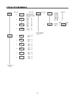
INPUTS
PROGRAM
........
INPUT 1
........
........
INPUT 2
........
INPUT 3
INPUT 4
Next item is PROGRAM
SER PORT on next page
OUT MODE
PROGRAM
RELAY 1
Repeated as shown
above for INPUT 1.
Repeated as shown
above for INPUT 1.
Repeated as shown
above for INPUT 1.
DISABLED
BYP P1
RS C EDG
RS C LVL
RS B EDG
RS T EDG
OUT CTRL
STOP CNT
LOCK PGM
LOCK ALL
READ (RPI)
20
21
22
23
WRITE (WPI)
200
201
202
203
204
205
206
207
208
209
21n
22n
23n
RELAY 1
NORMAL
REVERSE
LATCHED
PULSED
RELAY 1
RELAY 1
PUL
NA
PU
DO
RELAY 1
P1
READ
WRITE
300
301
302
303
3000
3001
3010
3011
3030
3031
3032
READ
WRITE (WPI)
32X
33X
Repeated as above for RELAY 1.
Repeated as above for RELAY 1.
TRANS 1
PROGRAM
TRANS 2
PROGRAM
32Xn
33Xn
RELAY 1
PB
RELAY 1
OCTRL
RELAY 1
RS C
NA
PU
DO
NA
PU
DO
NA
PU
DO
306
307
3070
3071
3072
305
3052
3060
3061
3062
3050
3051
302nnnn This screen is only available
if PULSED is selected in the above menu.
nnnn is a number from 0001 to 9999. If
nnnn=0000, then 1.00 is loaded.
d


