


10
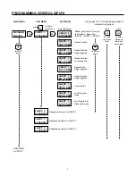
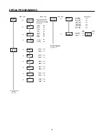
DESCRIPTION OF PROGRAM OPTIONS
SCALERS
C SCALER - the count scaler determines the value of each
input pulse. The counter displays whole numbers only. The
count scale factor affects the main counter and totalizer but
does not affect the rate meter. The count scaler’s decimal
point position is fixed.
C DEC PT - sets the decimal point position for the main
counter and totalizer. The decimal point position and scale
factor value are independent.
R SCALER - the rate scaler is used to adjust the rate meter
reading and compensate for the number of input pulses per
item. The rate scaler's decimal point is programmable. The
rate scaler and count scaler are independent.
R DEC PT - sets the decimal point position for the rate
display. The rate decimal point position and scale factor
value are independent.
COUNT INput
CONTACT ADD/SUB - input A adds counts and input B
subtracts counts. This mode includes input filtering to
debounce mechanical contacts.
CONTACT ADD/ADD - inputs A and B both add counts. This
mode includes input filtering to debounce mechanical con-
tacts.
CONTACT C/DIR - count with direction control. Input A adds
counts when the B input is high. Input A subtracts counts
when the B input is low.
SOLID ST QUAD x1 - requires a quadrature signal input. This
mode provides direction control and is used to eliminate false
counts due to jitter or vibration. The count direction depends
on the phase relationship of inputs A and B.
SOLID ST QUAD x2 - same as the quadrature x1 mode
above except that counts occur on both edges of input signal.
This allows increased resolution from the same pulse source.
SOLID ST ADD/SUB - same as the contact add/subtract
mode but can be used with high speed count signals.
SOLID ST ADD/ADD - same as the contact add/add mode
but can be used with high speed count signals.
SOLID ST C x1/DIR - same as contact count/direction but
can be used with high speed count signals.
SOLID ST C x2/DIR - same as above except counts occur on
both edges of input signal for increased resolution.
RESET TO ZERO - the main counter resets to zero when a
main counter reset occurs. The normal count direction is up
and the main counter outputs respond only when counting
up.
RESET TO P1( ) - the main counter resets to the preset value
when a main counter reset occurs. Preset coincidence oc-
curs when the main counter reaches zero. The normal count
direction is down and the main counter output responds only
when counting down.
Note: The Ambassador™ model 5760X-402 will not
actuate outputs that are assigned to preset 1 if the unit
is programmed to "Reset to Preset". This model will
actuate outputs normally when it is programmed to "Reset to
Zero". The reset destination is selected from the COUNT
INputs menu of the program mode. All other batch, total, and
rate functions operate without exception.
AUTO CYC DISABLED - the main counter does not auto-
matically reset when it reaches the preset value.
AUTO CYC P1(0) - the main counter automatically resets as
programmed when it reaches the preset 1 coincidence value.
The preset 1 coincidence value is zero when in the reset to
preset mode.
INPUTS
INPUT 1 DISABLED - input 1 does not perform any function
when turned on.
INPUT 1 OUT CTRL - when input 1 is turned on, an output
control signal occurs (edge sensitive). While more than one
input may be programmed for output control, only one output
control channel is available in the unit.
INPUT 1 RS C EDG - the main counter resets when input 1
is turned on (edge sensitive). If input 1 remains on, the main
counter can still count.
INPUT 1 RS C LVL - the main counter is held at the reset
value while input 1 is on (level sensitive).
INPUT 1 RS B EDG - the batch counter resets when input 1
is turned on (edge sensitive). If input 1 remains on, the batch
counter can still count.
INPUT 1 RS T EDG - the totalizer resets when input 1 is
turned on (edge sensitive). If input 1 remains on, the totalizer
can still count.
INPUT 1 STOP CNT - all count functions stop (inhibited)
while input 1 is on (level sensitive).


