


11
INPUT 1 LOCK PGM - all program editing is disabled
(keyboard and serial) while input 1 is on (level sensitive).
Preset values can still be changed serially or from the
keyboard.
INPUT 1 LOCK ALL - all programming and preset editing
functions (keyboard and serial) are disabled while input 1 is
on (level sensitive). The user can still select different run
mode displays from the keyboard.
Each of the previous functions is repeated for inputs 2, 3, and
4 respectively.
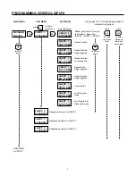
OUTput MODE
RELAY 1 NORMAL — relay 1 turns on when it receives a
pick-up signal and turns off when it receives a drop-out
signal.
RELAY 1 REVERSE — relay 1 turns on when it receives a
drop-out signal and turns off when it receives a pick-up
signal. The relay always powers-up in the off state.
RELAY 1 LATCHED — relay 1 turns on (off if reversed) when
it receives a pick-up signal and stays on (off if reversed) until
it receives a drop-out signal.
RELAY 1 PULSED — relay 1 turns on (off if reversed) when
it receives a pick-up signal and automatically turns off (on if
reversed) after the time specified below.
RELAY 1 PUL — enter the desired time for relay 1 to stay on
(00.01 to 99.99 seconds). This screen is not displayed unless
pulsed is selected in the menu above.
RELAY 1 P1 — relay 1 can be programmed for no action,
pick-up or drop-out when the main counter reaches the
preset.
RELAY 1 PB — relay 1 can be programmed for no action,
pick-up or drop-out when the batch counter reaches the
batch preset.
RELAY 1 OCTRL — relay 1 can be programmed for no
action, pick-up or drop-out when an output control signal
occurs. One of the inputs must be programmed for output
control before a RELAY 1 OCTRL can occur.
RELAY 1 RS C — relay 1 can be programmed for no action,
pick-up or drop-out when a reset main counter signal occurs.
The reset key or one of the inputs must be programmed to
reset the main counter before a RELAY 1 RS C can occur.
Each of these functions is repeated for transistor output 1 and
transistor output 2 sub-menus.
SERial PORT
SER PORT ID — enter the desired two digit serial ID number
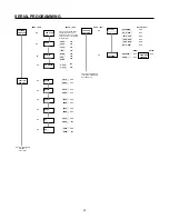
DESCRIPTION OF PROGRAM OPTIONS
(00-99 decimal). All communications to the control must
contain this number (in hexadecimal). Each unit must have a
unique ID#.
BAUD — selects the serial port transmit and receive baud
rate. Allowable rates are 19200*, 9600*, 4800, 2400, 1200,
and 300.
*Version 5 firmware or later. To check firmware version,
press "Help" key twice from run mode. First two digits (top
left) should read "25" or greater for version 5 or later.
PARITY — the user may select none, odd, or even parity. If
none (no parity) is selected, the counter transmits space
parity and does not check received parity.
Tx DELAY — The user may select a transmission delay of
either 2 or 100 milliseconds. The counter waits for this time
period before responding to any serial commands. This delay
is provided to allow a host computer time to switch from the
transmit to receive mode.
SERial OUT
These options determine which items are sent when the
counter receives the RCD7 command.
OPTIONS
RST KEY DISABLED — the RST/CLR key does not perform
any function.
RST KEY RS C EDG — the main counter resets when the
RST/KEY is pressed (edge sensitive). If the RST/KEY is held
on, the main counter can still count.
RST KEY RS C LVL — the main counter is held at the reset
value while the RST/KEY is pressed (level sensitive).
RST KEY RS B EDG — the batch counter resets when the
RST/CLR key is pressed (edge sensitive). If the RST/CLR
key is held on, the batch counter can still count.
RST KEY RS T EDG — the totalizer resets when the RST/
CLR key is pressed (edge sensitive). If the RST/CLR key is
held on, the totalizer can still count.
RST KEY D EDG — any counter value being displayed is
reset when the RST/CLR key is pressed (edge sensitive). If
the RST/CLR key is held on, the displayed counter can still
count.
USER/DEFAULT PROGRAM — If the user selects default,
the counter returns all program mode options to the factory
set values (first choice shown in menus). Counter and preset
values are not affected. This screen shows USER PRO-
GRAM if any options have been changed from the default
settings.


