


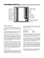


16
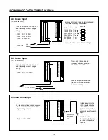
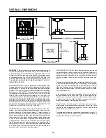
COUNT INPUT WIRING
Do not connect Term 1 if sensor is
powered from another power
supply.
Wire colors shown correspond to
Cutler-Hammer inductive proximity
and photo sensors.
All dip switches OFF.
Current Sinking Sensor
Count Input
Current sinking (open
collector NPN transistor)
sensor output
Black
+12 VDC Brown
DC Com Blue
Count
Signal
AC Signal Count Input
17 VAC RMS 48 V Peak-to-Peak
maximum into 2.3 K
Ω
load
impedance. Use an external
resistor (R) in series with the count
input signal for input voltages (V)
greater than 17 VAC.
R = (V x 230) - 2300
Dip switches 3 and/or 4 ON (AC
mode).
Dip switches 1 and 2 ON.
1
12
2
3
4
5
6
7
8
9
10
11
13
14
15
16
17
18
19
20
21
22
1
12
2
3
4
5
6
7
8
9
10
11
13
14
15
16
17
18
19
20
21
22
DC Com
Dotted lines indicate which
inputs may be wired in this
manner. Typically a separate
sensor is used for each input.
Control inputs (terminals
15-18) may be wired in the
same manner.
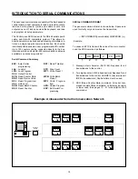
Do not connect Term 1 if sensor is
powered from another power
supply.
Wire colors shown correspond to
Cutler-Hammer inductive proximity
and photo sensors.
Dip switches 1 and/or 2 ON to
select current source mode,
switches 3 and 4 OFF.
Current Sourcing Sensor
Count Input
Current sourcing
sensor output
The output voltage of this
sensor must be between
3.5 and 17 VDC (100%
duty cycle) into a 2300
Ω
load. Use an external
resistor (R) in series with
the count signal for
voltages (V) greater than
17 VDC.
R = (V x 230) - 2300
Black
+12 VDC Brown
DC Com Blue
Count
Signal
1
12
2
3
4
5
6
7
8
9
10
11
13
14
15
16
17
18
19
20
21
22
Caution:
The unit requires 1.2 V P-to-P
minimum signal amplitude to
count. Magnetic pickups produce
an output voltage directly
proportional to the speed of the
ferrous material passing the
pickup. At low speeds, or at
starting or stopping, the output
voltage from the pickup may not
be great enough to cause the
counter to count. For magnetic
pickup signals in the range of 50
mV to 400 V P-to-P, a signal
conditioner (Durant part no.
48160-400) is recommended.


