


18
INTRODUCTION TO SERIAL COMMUNICATIONS
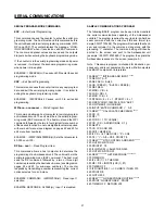
Serial Command Summary
ESP: Enter Serial
RST: Reset Totalizer
programming
LAL: Lock All
STP: Stop Count
LPG: Lock Program
WP1: Write Preset 1
OCL: Output Control
RCD: Read Counter Data
WPB: Write Batch
RDV: Read Device Value
Preset
RPI:
Read Program Item
WPI: Write Program
UAL: Unlock All
Item
RSB: Reset Batch Counter
UPG: Unlock Program
RSC: Reset Counter
XSP: Exit Serial Pro-
gramming
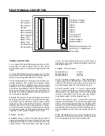
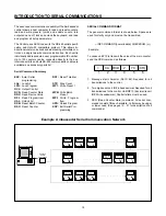
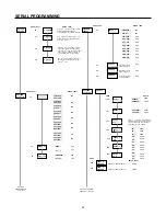
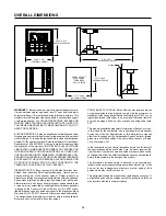
Example Ambassador Serial Communication Network
NO. 00
NO. 01
NO. 02
NO. 31
NO. 32
NO. 33
NO. 34
NO. 63
NO. 64
NO. 64
NO. 65
NO. 99
RS-485 TO
RS-232
CONVERTER
HOST COMPUTER
> 0A RCD 2 7C (CR)
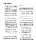
1 2 3 4 5 6
The advanced communication capability of the Ambassador
control allows a host computer to read and reset counters,
read and write presets, inhibit and enable counts, turn
outputs on and off, lock and unlock the keyboard, and read
and program all setup parameters.
The Control uses ASCII code with the RS-485 serial specifi-
cation and Opto-22 compatible protocol. This allows bi-
directional communications and addressing of multiple con-
trols on a single two-wire communication bus. Each unit is
individually addressed via a user programmable ID number.
Up to 100 counters can be connected directly to the bus.
Interconnect kits and bulk RS-485 communication cable are
available; see accessory parts list.
SERIAL COMMAND FORMAT
The general command format is shown below. Spaces are
used for clarity only and must not be transmitted.
> ID# COMMAND [numeric data] CHECKSUM (cr)
Example:
To cause unit# 10 to transmit the value of the main counter,
send the RCD command as follows:
1. Message start character (ASCII 62). Required for all
transmissions to the control.
2. Two digit serial port ID# in hexadecimal. Required for all
transmissions to the control. Unit ID# 10 (decimal) is unit
ID# 0A (hexadecimal). Capital letters must be used.
3. RCD (Read Counter Data) command. All serial com-
mands consist of three characters. Letters may be upper
or lower case. (See pages 19 - 21 for description of all
commands.)


