LCX9000 Liquid-Cooled Drives User Manual
4-16
For more information visit:
www.EatonElectrical.com
MN04005001E
January 2007
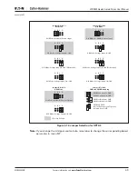
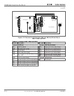
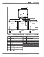
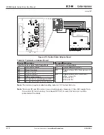
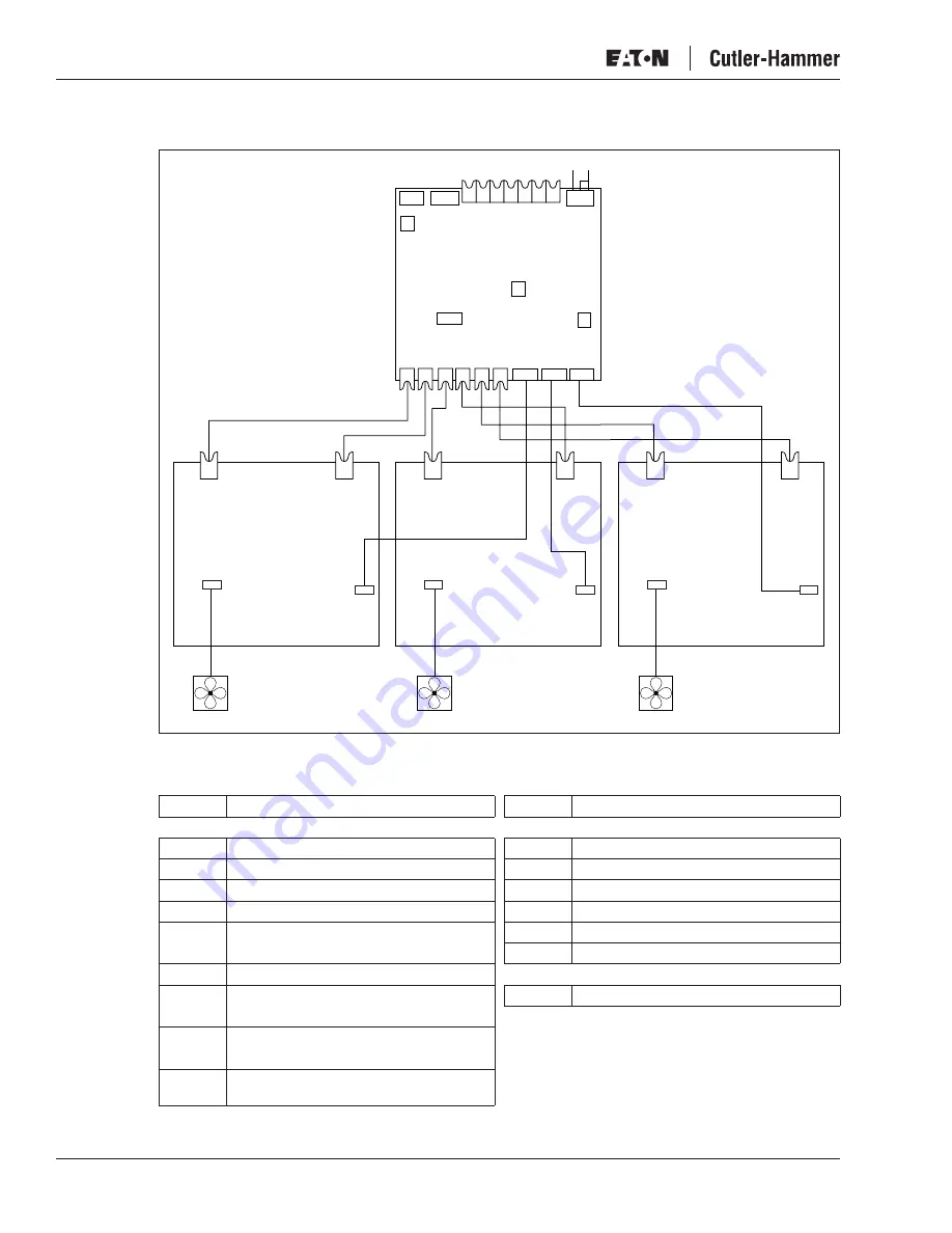
Figure 4-17: Terminals and Connections between ASIC and Driver Boards (CH64 and CH74)
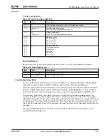
Table 4-5: Terminals between Driver Boards (CH64 and CH74)
Terminal Description
Terminal Description
Terminals on ASIC Board
Terminals on ASIC Board (Continued)
X9
OEVA feedback
UH
Connect to UH on Phase U driver board
X15
Charging relay output
UL
Connect to UL on Phase U driver board
X6
DC terminal
VH
Connect to VH on Phase V driver board
X29
Flow supervision input
VL
Connect to VL on Phase V driver board
X26
Star Coupler terminal for drives greater
than CH61
WH
Connect to WH on Phase W driver board
WL
Connect to WL on Phase W driver board
X10
+24V to control board
Terminal X2 on Phase Driver Boards
X3
Connect to terminal X1 on phase U
driver board
X2
Internal fan power connection
X4
Connect to terminal X1 on phase V
driver board
X5
Connect to terminal X1 on phase W
driver board
X9
X15
X29
H1 H2 H3 H4 H5 H6 H7
X6
DC- DC+
A
S
IC Board
X26
X1
X10
UH
VH
WH
UL
VL
WL X3
X4
X5
Driver Board,
Phase U
Driver Board,
Phase V
Driver Board,
Phase W
VH
UL
X2
X1
X2
X1
X2
X1
UH
WH
VL
WL
Module 2
Module 3
Module 1
I
n
ter
n
al Fa
n
I
n
ter
n
al Fa
n
I
n
ter
n
al Fa
n


