86
8 Operating
Mounting and Operating Instructions CEAG Central Battery System ZB-S 40071860179 (L) November 2018 www.ceag.de
Overview:
Main menu
Test & status menu
Block & reset alarms
Basic settings
DLS/TLS Setup
Circuit setup
Luminaire setup
Logbooksetup
Send ServicePinMsg
Menu 3
Language
Date & time
Functiontest
Durationtest
Delay time mains
return
Manual reset
Selective EmgcyOper.
Relay setup
Buzzer setup
Display setup
Charger setup
Printer setup
Relay module setup
Webserver setup
Timer setup
Substation setup
Connection to BMS
Function keys
Optional inputs
Serialnumber & type
Password protection
Daylight saving time
Service info
Selection of
menu options
with the
keys
<ok>:
confirm selec-
tion
<Menu>: can-
cel and return
to the previous
menu (any
changes en-
tered are saved)
<ESC>: cancel
and return to
the previous
menu (any
changes en-
tered are not
saved)
flashing input
prompt
<ok>
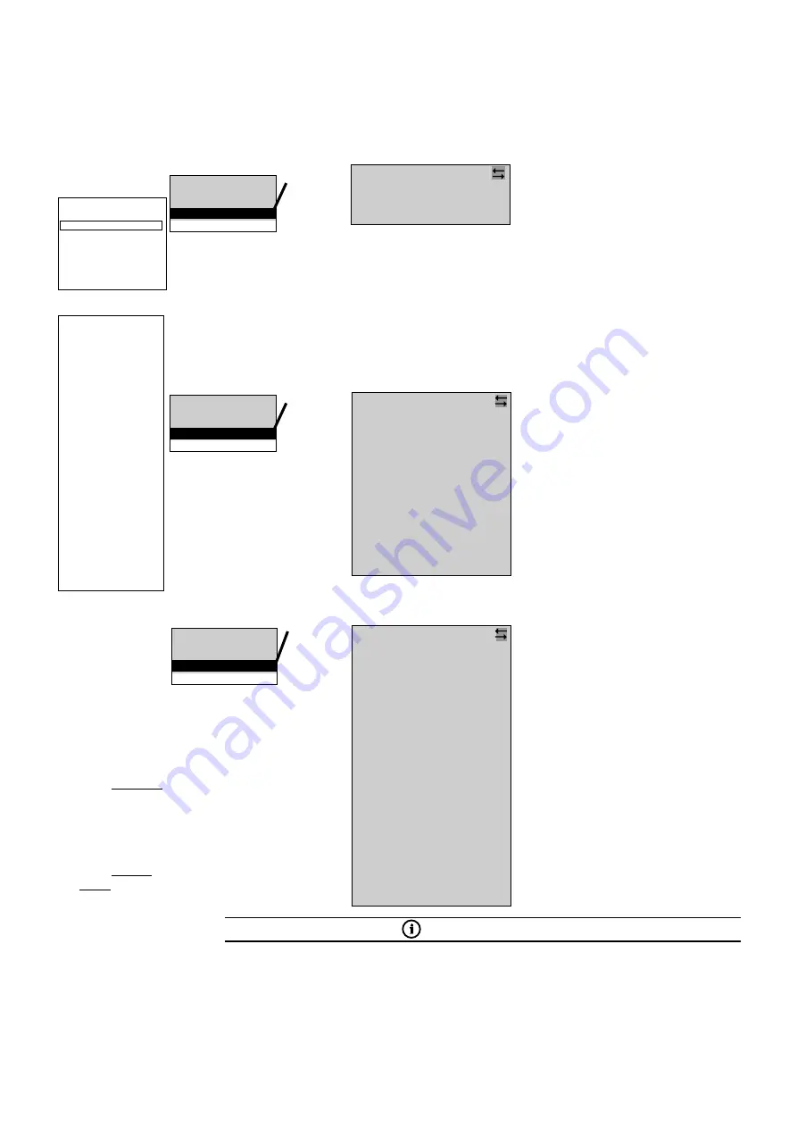
Menu 3.17:
This menu is used to activate and inter-
face the system with a master monitor-
ing device using the CG-S bus or the M3
function.
Line selection (1 / 2) with
Select a device (bus) address (1 ... 32)
in line 1 with keys
(display — :
no interface)
Select no/yes in line 2 for the option
LON switch with
Line 4: Device name user-definable.
See text assignment 4.2
Finish and return to Menu 3 with
<Menu>
ote:
N
The entries in lines 3 and 4 are for
information for the system integra-
tor only.
Device address: 1
LON switch no
NID00 05 94 75 52 00
Device name
Webserver setup
Timer setup
Substation setup
Connection to BMS
Function keys
This menu option can be used to assign
functions to the function keys (F1...F3 on
the control module); the functions are
executed as soon as the relevant key is
pressed.
It is advisable to assign only one function
per key; the star icon goes out when a key
is assigned another function.
Select the function key (1 to 3) with
keys
Highlight the function with
Select the function (
) with <ok>
Finish and return to Menu 3 with
<Menu>
Timer setup
Substation setup
Connection to BMS
Function keys
etc....
<ok>
Menu 3.18:
Function key 1
No function
Switch
Block device
Simul mains fail MDB
ISO failure reset
Manual reset
Deep discharge reset
F-Test without lead
Show fault list
Turn off maintained light
Standby light on
This option can be used to assign functions
to the option inputs (Z1 ... Z4 on the control
module); the functions are executed as
soon as the relevant 24V analog inputs are
triggered.
Only one function can be assigned per
input; the star icon goes out when an input
is assigned another function.
Select the option input
(1 to 4) with keys
Highlight the events with
Select the function (
) with <ok>
Finish and return to Menu 3 with
<Menu>
Substation setup
Connection to BMS
Function keys
Option inputs
etc....
<ok>
Menu 3.19:
Switch
Switch inverted
Manual reset
Deep discharge reset
F-Test start
B-Test start
B-Test cancel
Block device
Maintained off
Non-maintained on
Ventilator monitor
Ext. ISO monitor
Ext. Battery Monitor
Ext. Monitor
All Luminaires On
AE Scenario activ
AE Error
1
)
2
)
3
)
Notes:
1
) The “Switch” assignment allows integration into the switch assignment (see menu options 5.4 and 6.3
“Switch assignments” in menus 5 “Circuit setup” and 6 “Luminaire setup”.
2
) The “Switch inverted” assignment initiates the function when the analog inputs are triggered inverted.
3
) For connection of the AE-CU Controller the AE-CU Relaismdoule have to be mounted in the ZB-S.
IMPORTANT NOTE
The “Switch”, “Switch inverted”, “Ventilator monitor”, “Ext. ISO monitor”, “Ext. Battery Monitor”,
“Ext. Monitor” functions require a 24 V level trigger. All other functions require an edge-triggered signal
from LOW to HIGH.
Option input 1
No function


