2
Instruction Leaflet
IL019226EN
Effective October 2018
C-HRG technical information
and adjustment procedure
EATON
www.eaton.com
Receiving, handling, and storage
CAUTION
TALL, NARROW STRUCTURE—MAY TIP OVER IF MISHANDLED. MAY
CAUSE BODILY INJURY OR EQUIPMENT DAMAGE. DO NOT REMOVE
FROM SKID UNTIL READY TO SECURE IN PLACE. READ HANDLING
INSTRUCTIONS BELOW BEFORE MOVING.
Configurations
•
Freestanding, single enclosure (NEMA Type 1, NEMA Type 3R)
•
Wall-mounted control enclosure with separate wall-mounted
resistor enclosure (both NEMA Type 1)
•
Incorporated into a switchboard or switchgear assembly
Shipping weights:
•
Freestanding: 650 lb (294.84 kg)
•
Wall-mounted: 250 lb (113.4 kg), control assembly
•
75 lb (34.02 kg), resistor assembly
Packing method:
Plastic overwrapped, suitable for standard truck transportation and
indoor storage (all). Freestanding is bolted to fork-liftable skid. Skid
adds approximately 4.00 inches (101.6 mm) to overall height.
Lifting
Unit may be lifted by the top-mounted lifting angles or moved into
place with a forklift. The unit is a tall, narrow enclosure that can
be tipped over if mishandled. For additional stability, keep it on its
shipping skid until it is moved into place.
Unit may be rolled by placing pipes under the longitudinal skid
members in at least four places, evenly spaced. As one pipe comes
free, replace it ahead of the unit. Keep at least three evenly spaced
pipes under the unit at all times.
Once the unit is in place, remove and discard the lifting angles.
Replace the hardware to plug the exposed holes.
Storage
Choose a location that is suitable for indoor-type electrical
equipment. (Note: treat a NEMA 3R unit as if it were indoor-type
equipment until it is to be energized.) If the location is unheated, do
not allow condensing humidity on or within the equipment. Provide
sufficient heat and moving air to prevent condensation. Once the
unit is energized, it will provide the required heat internally.
Installation
Unpacking
Remove plastic overwrap. Inspect for shipping damage. Report
any damage immediately to the carrier and be sure to save the
packing materials until inspected by the carrier. Inspect cover
and compartment-mounted devices for blocking or other packing
materials. Place all documents in the document pocket.
Equipment location
Observe all the appropriate codes with respect to clearances on
all sides. This equipment is front accessible, meaning that side
access is not required for installation and maintenance. When
choosing the location for a separately mounted resistor assembly,
keep in mind that it will give off considerable heat. Do not mount it
on a combustible surface or adjacent to heat-sensitive material or
equipment.
Walls or floor must be sufficiently level to allow doors and covers to
remain properly aligned with the structure. If embedded channel-iron
floor sills are used, they must be at or above floor level.
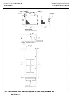
Refer to assembly drawings provided with the unit for bolt-down
hole locations. Bolt directly to wall or floor or channel-iron floor
sills. Use 1/2-inch or 3/8-inch bolts for freestanding units and
3/8-inch bolts for wall-mounted units. If floor sills are used, unit
can be welded to channels. Use sufficient weld bead to approximate
the strength of one 3/8-inch SAE grade 5 bolt at each corner.
Seismic
If unit is furnished for suitable use in a seismic zone, refer to seismic
installation guidelines referenced on the assembly drawing provided
with the unit. Seismic installations supersede all other instructions.
Wiring
SAFETY PRECAUTIONS:
ONLY PERSONS TRAINED AND EXPERIENCED IN THE
SERVICING OF ELECTRICAL DISTRIBUTION EQUIPMENT
SHOULD ATTEMPT TO SERVICE THIS EQUIPMENT.
DANGER
HIGH VOLTAGE!
WILL CAUSE DEATH, BODILY INJURY, OR EQUIPMENT DAMAGE.
TURN OFF POWER AT THE SOURCE BEFORE WORKING INSIDE.
Use the schematic provided with the unit to determine the wiring
interconnections required. All wiring must be in conformance
with the NEC
T
and/or local codes. Minimum wire sizes required
are indicated on the schematic and must conform to the
following minimum guidelines (based on 75 °C copper, per
2011 NEC Table 310.15(B)(16)):
•
Neutral: 8 AWG
•
Ground: 8 AWG
•
Phases: 12 AWG
Terminal block wire ranges:
•
Neutral: #8
•
Ground: #8 to 500 kcmil
•
Phases: #12 to #8
•
Control: #22 to #8
Alarm contact ratings:
•
600 Vac (A600) 10 A continuous
7200 VA make / 720 VA break
•
250 Vdc (P300) 5 A continuous
1.1 A at 125 Vdc make/break
0.55 A at 250 Vdc make/break
Final inspection and test log
•
Turn all disconnects off. Perform any testing as directed by others
•
Inspect for loose or missing connections
•
Inspect all compartments for debris, tools, and so on
•
Replace all covers removed during installation
•
Energize when directed to do so, and make all adjustments (refer
to “Adjustment Procedure” section of this instruction manual)
Using the test log provided (
) or a similar format of your
choosing, test the unit and make the first entries. A document
pocket is provided on the back of the control compartment door.
Leave the test log (or a copy of it), a copy of the drawings, and a
copy of this instruction manual in the pocket. Store the optional
clamp-on ammeter in a clean, dry place. Do not store it in the control
or resistor compartment.


