8
Instruction Leaflet
IL019226EN
Effective October 2018
C-HRG technical information
and adjustment procedure
EATON
www.eaton.com
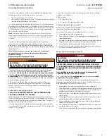
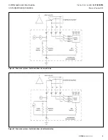
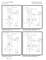
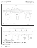
Figure 2. Illustration of the leakage current in a system
Figure 3. Capacitive charging current and ground return current
This method follows Baldwin Bridger’s paper on determining the
charging current of a system [1].
Setting the current relay and voltage relay
WARNING
HIGH VOLTAGE!
MAY CAUSE DEATH, BODILY INJURY, OR EQUIPMENT DAMAGE.
TURN OFF POWER AT THE SOURCE BEFORE WORKING INSIDE.
Only qualified personnel should attempt to service
energized equipment.
1. De-energize the C-HRG equipment.
2. Set the time delay to minimum. There may be an additional timer
in the control circuits, and for voltage relays the control circuit
timer is the only timer.
3. Set the current one setting above the expected ground return
current that was established using resistor taps—each tap
corresponds to a current value (as shown in “Resistor taps”
section). For a voltage relay, use the corresponding voltage,
which is the current to be allowed on the circuit × the
resistance previously set with resistor taps (see note).
Example: if the allowed ground return current on the system
is 3 A, set the current relay to 4 A.
4. Re-energize the equipment.
5. Put the C-HRG in “test” mode.
6. Make sure the selector switch is held in “test” position. The
switch has a spring-return to normal position and must be held
in “test” position.
7. The relay should not pick up the test current.
8. De-energize the equipment.
9. Set the relay to one setting below the allowed ground
return current.
10. Re-energize the equipment.
11. Put the C-HRG in “test” mode and hold the switch in
“test” position.
12. The relay should pick up the test current, the alarm lights
will go on, and the optional horn will sound.
13. Reset the alarm using the reset switch.
14. This proves that the relay works.
15. De-energize the equipment.
16. Choose a desirable pickup point below the allowed ground
return current and set the time relay to a desirable level to
avoid nuisance trips.
ote:
N
There is an additional resistance of 10 Ω in the test circuit. When
calculating the voltage
in TEST MODE
using the voltage relay, it should
be taken into consideration. For example, at step 3, a 3 A ground return
current and 4 A setting on the current relay
ONLY IN TEST
MODE
has a
corresponding voltage of 4 A × (89.5 Ω - 10 Ω) = 318 V. The 89.5 Ω resistance
is associated with 3 A ground return current. The relay should not pick up as
that was the purpose of step 3.
The calculations in TEST MODE should
always take that resistance into consideration for accuracy.
To set the
voltage relay
in NORMAL MODE
, the test resistance of 10 Ω should no
longer affect the circuit.


