3
Instruction Leaflet
IL019226EN
Effective October 2018
C-HRG technical information
and adjustment procedure
EATON
www.eaton.com
Components
SAFETY PRECAUTIONS:
ONLY PERSONS TRAINED AND EXPERIENCED IN THE
SERVICING OF ELECTRICAL DISTRIBUTION EQUIPMENT
SHOULD ATTEMPT TO SERVICE THIS EQUIPMENT.
DANGER
IF YOU ARE NOT QUALIFIED AND AUTHORIZED TO SERVICE THIS
EQUIPMENT, DO NOT DO SO. YOU AND/OR OTHERS COULD BE KILLED
OR OTHERWISE SERIOUSLY INJURED AND/OR PROPERTY DAMAGE
COULD RESULT.
DANGER
HIGH VOLTAGE!
WILL CAUSE DEATH, BODILY INJURY, OR EQUIPMENT DAMAGE. TURN
OFF POWER AT THE SOURCE BEFORE WORKING INSIDE.
Not all systems will have all components. Check bill of material or
schematic for features included in your specific system.
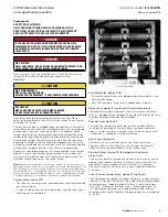
Resistors
CAUTION
HIGH TEMPERATURES!
MAY CAUSE SERIOUS BURNS.
ALLOW RESISTOR ASSEMBLY TO COOL DOWN BEFORE SERVICING.
CAUTION
FIRE HAZARD!
MAY CAUSE FIRE OR SEVERE EQUIPMENT DAMAGE.
DO NOT EXCEED RESISTOR CURRENT RATINGS.
Note the current rating stamped on each resistor’s tag. Do not
adjust resistance below a level that will allow current in any resistor
to exceed that rating.
The resistor assembly is shipped ready to use and set at the ohmic
value shown on the schematic. User adjustments will not, in general,
be required. If, however, minor adjustments are needed, loosen
jumper on resistor tap terminal block, and move the position of the
jumper to desired tap setting. Beware of parallel paths created after
attaching the jumper. The ohmmeter may not show the resistance
expected. A simple calculation of parallel impedances will clear this.
In order to avoid doing any calculations, check the resistances before
attaching the jumper and verify if they conform to expectations.
Readjust as required and replace the wire connection. Each resistor
tube has a metal tag showing the part number, ohmic value, and
maximum rating; do not adjust any resistor to an ohmic value that
will allow current in excess of the current rating.
ote:
N
During initial usage, the resistors may “smoke” for the first hour or so,
depending on the current. This is normal and comes from residual process oils
and the curing of the resistor tube insulation. Lower current levels may allow
the initial burn-off to occur gradually with little or no visible smoking. Smoking
may reoccur after the initial burn-off if dust or other contamination is allowed
to accumulate. Refer to maintenance procedures outlined in this manual.
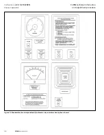
Current relay, device 51N
•
The relay has two adjustment potentiometers—one for pickup and
one for time delay
•
If relay has plugs over the adjustments pots, replace them when
adjustments are completed
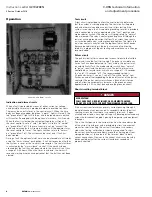
Resistor assembly
Voltmeter relay, device 59N
•
This meter/controller has user-programmable parameters all set
from the front panel
•
Four LED indicators for up to four independent set points
Delay timer, device 2 (systems with voltmeter relays)
The voltmeter relay does not have a built-in time relay, therefore
relay 2 is provided for that purpose. The knob on the top of the relay
will allow selection of the desired time delay.
Recycle timer, device 95
This relay has two adjustment knobs, one for on-delay and one
for off-delay. The output of the relay drives the pulser contactor
(relay 4). In most systems, a pulsing rate of 30 pulses per minute
(1 second on, 1 second off) will be satisfactory.
Alarm horn (optional)
The horn has a small setscrew on its front face, for which a
setscrew wrench is furnished. Turn the setscrew clockwise to
soften the tone and counterclockwise for a louder tone.
Re-alarm timer, device 74 (furnished with optional
alarm horn)
If the system detects a ground and sounds the alarm horn, and an
operator then silences the horn, this relay will cause the horn to
resound in a certain amount of time if the fault is still present.
The timer is typically set for 24 hours, and is knob-adjustable for
2–48 hours.
Loss of control power relay, device 27 (optional)
If the control power voltage falls below the relay’s setting, the relay
contacts will transfer. The contacts are wired to terminal block points
for customer use. Dropout (marked “setting”) is adjustable from
75 to 100%. Differential (marked “reset”) is adjustable from 1 to
15%. Both potentiometers are screwdriver-adjustable, and are
mounted on the front of the relay. The percentages are in reference
to 120 Vac.


