EATON Airflex WSB 11210 WCSB3 Installation Operation and Maintenance E-CLCL-11001-E October 2013
27
(d)
Step Four: Finish torque tightening by selecting
a starting position (usually at the 12 o’clock position)
and check the 100% torque of each screw going in
a sequential clockwise or counterclockwise rotation.
Mark or highlight screw head or nut & shank after
final torque check as a visual indication that the
screw/nut has been tightened to specification shown
in Table 15.
4.5.8 After completion of the assembly, each water cavity
should be checked for leaks per static test in 3.4.6.1.
4.5.8.1 Using lifting straps, suspend each assembly with
the water outlet port at the 12 o’clock and 6 o’clock
position. Connect a water supply line to the inlet port
at the 6 o’clock position. Plug the side ports and leave
the 12 o’clock port open to purge air from the coolant
cavity. See Table 16 for outlet port sizes.
4.5.8.2 Slowly fill with water to purge all air from water
cavities
4.5.8.3 Install an ORB pipe plug in 12 o’clock port and
apply appropriate water pressure (40 psig (2.76 Bar)
for the 36WCSB3. Pressure is measured at the inlet.
Maintain this pressure for a minimum of 30 minutes.
4.5.8.4 Check for leakage at the O.D. and I.D. seal areas. No
leakage is allowed.
4.5.8.5 If the assembly leaks, check the torque on each
screw and re-test. If leaks still occur, the wear plate(s)
or sealant tape or iron surface may be damaged.
Repair and repeat procedure from 4.5.2.
4.5.8.6 Follow steps in Section 4.8 to reassemble the
tensioner.
Caution
After replacement of wear plates (3), a wear-in period
is required per Section 3.3 for the friction couple to
achieve rated torque.
4.6
Seal Replacement
Note: The cylinder piston seals (21) & (23) can be replaced with
the brake fully assembled and simply removing the cylinder (19)
while the rest of the brake remains assembled. If the piston seals
in the mounting flange/cylinder (112) require replacement, full
disassembly of the tensioner is required. See Section 4.3.
4.6.1 Cylinder Seals
4.6.1.1 Disconnect the air supply lines and match mark
the cylinder to a stud or other component to ensure
proper orientation during reassembly. Remove the
screws (20), washers (17) and spacer tubes (27)
attaching the cylinder (19) to the pressure plate (13).
4.6.1.2 Carefully slide the cylinder off of the spring housing
(16) or piston (33) out of the mounting flange/
cylinder (112).
Caution
Do not use compressed air to remove the cylinder
from the spring housing.
4.6.1.3 Remove the cylinder seals from the spring housing
(16) or piston (33) and thoroughly clean the seal
grooves in the piston or spring housing.
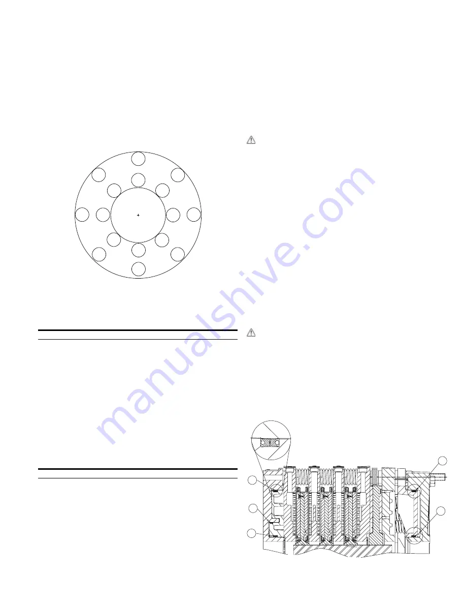
4.6.1.4 Insert new seals into the grooves, noting the
orientation of the seals per Figure 13.
12
16
2
3
9
5
8
10
11
6
14
15
7
1
4
13
Figure 12
Table 15
Wear Plate Fastener Size & Torque
Model
Size
Torque Ft-lb (Nm)
36WCSB3
3/8-16NC2*
40 (54)
*Alloy Steel Grade 8
Table 16
Inlet & Outlet Coolant Port Sizes
Model
Size O-ring Boss (ORB)
36WCSB3
SAE-20 J1926
LIP SEAL TYPICAL CONFIGURATION
23
114
21
23
21
Figure 13
WCSB3 Brakes


