DPD-9E2305
16
•
•
•
•
5.6 UPS remote control functions
Connectivity cards
Connectivity cards allow the UPS to communicate in a variety of networking environments and with different types of
devices. The 9E models have one available communication bay for the following connectivity cards:
Gigabit Network card
(
Network-M2, Network-M3
) : provides a Gigabit Ethernet connection and enables secure UPS
monitoring over HTTPS web browser interface, SNMP v1/v3 protocol and email alarms. In addition, up to 3
Environmental Monitoring Probes can be attached to obtain humidity, temperature, smoke alarm, and security
information.
Industrial Gateway card
(
INDGW-M2
) : Provides Modbus RTU and Modbus TCP communication support in addition
to the same secure UPS monitoring, management and sensor capability as the Gigabit Network card.
Relay-MS card
: provides isolated dry contact (Form-C) relay outputs for UPS status: Utility failure, Battery low, UPS
alarm/OK, or on Bypass.
INDRELAY-MS
: The Industrial relay Card-MS (INDRELAY-MS) provides a simple way to remotely input UPS information
to an alarm system, PLC or a computer system via dry contacts. It offers five isolated dry contact outputs and one
isolated dry contact input.
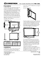
Remote control connection and test
Check that the UPS is OFF and disconnected from the AC input source.
Remove connector (4) after unscrewing the screws.
Connect a normally closed volt-free contact (60 V DC / 30 V AC max., 20 mA max., 0.75 mm2 cable cross-section) between
the two pins of connector (4) (see diagram).
Warning. This connector must only be connected to SELV (Safety Extra-Low Voltage) circuits.
Contact open: UPS shutdown, LED
turns ON
To return to normal operation, deactivate the remote
external contact and restart the UPS by pressing button