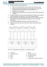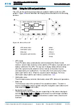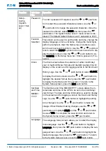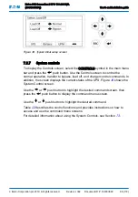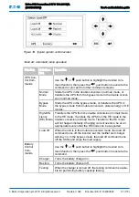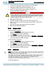
Figure 35. UPS control panel
1
Status indicators
3
Navigation push buttons
2
LCD display
The control panel consists of:
• A liquid crystal display (LCD)
• Menu navigation push buttons switches
• A vertical column of status indicators. See Section
The following sections describe how to use the UPS control panel to monitor the
UPS.
When the unit powers up, the screen displays the Eaton logo. To advance to the
main menu and the Mimic screen, press any control panel push button once.
7.2.1
Status indicators
The four symbols below the display are status indicators. They are colored light
emitting diode (LED) lamps, and they work in conjunction with the alarm horn to
let you know the operating status of the UPS.
Table 19: Status indicators
Indicator
Status Description
Green symbol for normal
operation
On
The UPS is in the Double conversion (Normal),
HE, or stored energy mode. The UPS is operating
normally and supplying power to the critical load.
Off
The UPS is turned off.
Note: The UPS could still be in the bypass
mode when the LED is off.
Yellow symbol for battery
mode
On
The UPS is in the stored energy mode. Because
the stored energy mode is a normal condition of
the UPS, the green indicator for normal operation
also remains illuminated.
Eaton 93E Generation 2 UPS 100-200 kVA
(380/400/415V)
User's and installation guide
©
Eaton Corporation plc 2019. All rights reserved.
Revision: 002
Document ID: P-164000848
78 (118)


