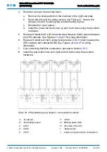
Figure 26. UPS paralleling wiring diagram – without parallel tie cabinet
A UPS 1
D UPS 4
B UPS 2
E Terminating jumper
C UPS 3
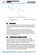
Figure 27. Parallel UPS system connections
1
Cabling to UPS bypass input
3
Cabling to UPS rectifier input
2
Outputs from UPSs
4
External battery cabinet(s)
5.3.3
Installing MiniSlot interface connections
For the installation and setup of a MiniSlot card, contact your Eaton
representative.
To install wiring:
1.
If not already installed, install the LAN drops. The LAN drop is to be
supplied by the customer.
2.
Route and install the LAN and other cables to the appropriate MiniSlot
.
3.
For operator instructions, refer to the manual supplied with the MiniSlot
card.
Eaton 93E Generation 2 UPS 100-200 kVA
(380/400/415V)
User's and installation guide
©
Eaton Corporation plc 2019. All rights reserved.
Revision: 002
Document ID: P-164000848
67 (118)


