200
200
200
200
Step
Step
Step
Step 4:
4:
4:
4: Connecting
Connecting
Connecting
Connecting
2.
2.
2.
2.
A specific function block is selected using the
symbol bar.
3.
3.
3.
3.
The following symbol now appears in the work
area:
Now, move the cursor to the required
position.
The function is inserted by clicking the left mouse
button.
1.
1.
1.
1.
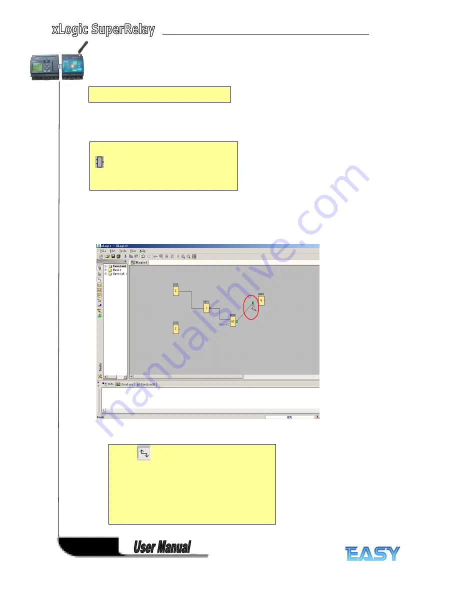
The
tool must be selected if you want to
connect the inputs and outputs of the function blocks
to one another. Now point the mouse to a connection
pin of a block and click using the left mouse button.
Keeping the mouse button pressed, move the cursor
until it is pointing at the pin that you want to connect
to and release the mouse button.
xLogic
then
connects the two pins together. This results in a
connection between two block pins. Use the same
procedure for the other connections.
Содержание xLogic
Страница 1: ......
Страница 2: ......
Страница 102: ...100 100 100 100 B B B B Blocks Blocks Blocks Blocks...
Страница 105: ...103 103 103 103 G G G G M M M M status status status status...
Страница 106: ...104 104 104 104 H H H H AM AM AM AM value value value value...
Страница 164: ...162 162 162 162 If the Memory Read block had been triggered the Q1 of ELC 12 CPU will be set 1...
Страница 204: ...202 202 202 202 Step Step Step Step 6 6 6 6 Moving Moving Moving Moving...
Страница 226: ...224 224 224 224...


