background image

8

®

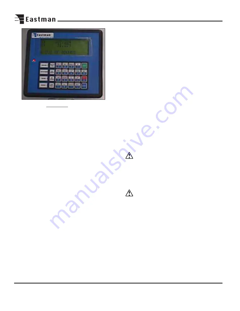
User Interface Terminal Familiarization
The UIT (User Interface Terminal) features a 33 key mem-
brane keypad and a four line display. Commands are issued
via the keypad and information is communicated back to
the user through the display. Through the UIT the operator
may position the plotter carriage, enable automated move-
ment, and manually cut and mark.

Commands are sent to the computer by pressing specific
keys or key sequences on the UIT. Each key on the UIT can
have a function and characters related to that key (note that
not all keys have both a function and characters). Com-
mands that require data entry following the pressing of a
FUNCTION key the UIT will automatically set itself in antici-
pation of the expected type of input.

Some commands require only one key to be pressed while
other commands require multiple keystrokes and may some-
times prompt the operator for input.

A description of commands follows:

SET ORIGIN: Press to set the first label position on the

table. The laser pointer marks the origin position. To
adjust offset, see software section.

ZERO TABLE: Press to activate the zeroing function on

the carriage. The carriage will move to the home limit
switch cam. This point is set as home position.

SPEED: Press to set fast/slow machine movement.

/6: Press to move labeler head away from operator.

/9: Press to move Labeler head toward the operator.

MOVE: Press to access menu.

Press 1 to send SLS 2 to home position.
Press 2 to send SLS 2 to label origin position.

UP: Pressing UP causes the elevator to move up.

DOWN: Pressing DOWN causes the elevator to move down.

LEFT: Pressing LEFT causes the SLS 2 Labeler to move to

the left.

Right:: Pressing RIGHT causes the SLS 2 Labeler to move

to the right.

START: Press START to begin automatic labeling mode.

NEXT: Press to resume automatic labeling when machine

pause is pressed.

ABORT: Press to abort command.

ENTER: Press ENTER to accept command.

Operation
After setup is complete and the power and airline is con-
nected, the SLS 2 is now ready for Initialization.

Important

To stop the SLS 2 at any point during
operation, either:
-Press the Emergency Stop button (Red).
-Hit Machine Sop Wands.
-Press Machine Pause button (yellow) on main control
panel.

WARNING: Safety cams should always be checked

for proper operation with the SLS 2 before any automatic
labeling takes place.

Activate battery back-up to ON (I) position. Activate the
computer by pressing the ON (I) button. The computer
display will run through the computer start-up program.

Pull the Emergency Stop button to activate power to the
drive circuit. Start the EASICUT software by double clicking
the EASICUT software icon on the computer display. This
will load the default test.cmd file. Enter label text for the
required fields using the keyboard. Select OK.

The log in screen will appear. Enter the user name and pass-
word. Select OK when complete. The UIT Display will show
DESIGN LOADED. Press ENTER on UIT Terminal to con-
tinue.

UIT Terminal

Содержание ETS-SLS-2

Страница 1: ......

Страница 2: ...ould be instructed to wear safety glasses and stand well clear of the SLS 2 Stack Labeler when in operation Table of Contents Safety Information 3 INSTALLATION 4 Table Preparation 4 Place Machine on Table 4 Guide Wheel Installation 4 Safety Cam Home Limit Switch Installation 4 Encoder Track Installation 5 Encoder Assembly Installation 5 Cable Carrier Installation 5 Machine Familiarization 6 SLS 2 ...

Страница 3: ...s losses expenses damages and liabilities to the extent that they have been caused by the purchaser s fail ure to comply with the terms and instructions of this manual General Safety Precautions WARNING This machine is equipped with fast moving labeler head Keep hands arms and hair away from the labeling area and drive system at all times Safety gloves glasses and appropriate clothing may pre vent...

Страница 4: ...and the forklift arms should be raised to those braces when machine is lifted CAUTION When placing forklift arms under cross channels use care not to damage tension rods or cover WhentheSLS2StackLabelerisshippedtheStopWands StopCams CableCarrierKitandGuideWheelAssemblies are removed and must be installed upon installation Place the SLS 2 Stack Labeler on table between end markers marks designating...

Страница 5: ...along encoder gear belt Fastenbracketwithhardwareprovided Adjusttension so gear wheel remains in continuous contact with gear belt as the SLS 2 moves Cable Carrier Installation BeforetheCableCarrierKitcanbeinstalledthetablelegson the non operator side must be modified Drill two 2 7 32 diameterholesineachtablelegasshown Locatethecable carrier trough mounting brackets and mounting screws Assemble ea...

Страница 6: ... Reserve power in the event main power is interrupted 10 minute minimum supply Emergency Stop Activates power to all drive circuits Pull on push off On Board Control Components Electrical components used to control the SLS 2 labeling system Labeler Tool Head Tool used to apply labels to material Machine Stop Wands Deactivates power to all drive circuits when wand strikes object in its path Stop Li...

Страница 7: ...d labeling files Emergency Stop Activates power to all circuits Pull on Push off Auxiliary Switch Available for future use Joy Stick Control For manual movement of machine and labeling head Machine Pause Push to stop machine when in automatic labeling mode Press NEXT on UIT to resume Labeler Error Indicator Indicates error in label position Press label feed to reset Printer On Off Press to activat...

Страница 8: ...r MOVE Press to access menu Press 1 to send SLS 2 to home position Press 2 to send SLS 2 to label origin position UP Pressing UP causes the elevator to move up DOWN Pressing DOWN causes the elevator to move down LEFT Pressing LEFT causes the SLS 2 Labeler to move to the left Right Pressing RIGHT causes the SLS 2 Labeler to move to the right START Press START to begin automatic labeling mode NEXT P...

Страница 9: ... This will raise the elevator to the top position and accelerate machine to the machine home position Note The Machine Home Position is created when the Home Limit switch strikes the Stop Cam mounted on the table The UIT display will show TABLE ZERO OK when task is complete Press enter on UIT terminal to except The UIT display will show ready Set Origin location of first label Press the Printer ON...

Страница 10: ...or loose nuts and bolts Check table and track for loose or damaged parts Monthly Inspect Cable Carrier loose nuts bolts or worn parts Check oil level in gear reducer fill if necessary Recommended Spare Parts List Item Description Qty 9013 006 Encoder Belt A R 65 11 1168 Limit Switch Printer Head Down Limit 1 54 26216 Roller Quick Release Pin 1 54 26031 Spring Clip Label Take up Roller 1 67 26060 1...

Страница 11: ...tes DESIGN CMD every time the plotter operator loads a new cut pattern CMD is Eastman Technology s proprietary file format Easicut to CMD automatically converts files gener ated in other formats when the plotter operator selects them MACHINE INI contains values pertaining to calibration ve locity profiling table dimensions and layer to tool mapping Easicut writes to this file as changes are made i...

Страница 12: ...pen another file for viewing without chang ing the plotted file Likewise closing a file does not remove it from the plotter To determine which file is currently plot ted look at the Control Panel or the Plotter Status in the lower part of the main screen 3 The Project menu is similar to the File button except that it works with groups of files called projects The user specifies projects with the P...

Страница 13: ...e repeats the label pattern con tinuously on the table The Project Manager tab The Project Manager is used to edit projects Files may be added to or deleted from a project Preview will display the selected file in the marker window The Edit button features a file name editor a material type selection and comments The Plotter Status tab The Plotter Status tab is essentially a more detailed read out...

Страница 14: ...controls how fast the plotter goes around corners If the plotter crashes while making a turn this number must be decreased Conversely throughput may be slowed if Accel G Arc is set too low Accel G Max Controls acceleration on short movements where the plotter won t be reaching its maximum velocity These movements may be made a higher than normal ac celeration Generally speaking this number can be ...

Страница 15: ...steps to travel one centimeter causing inaccuracy in the length of cut panels The correct number for this calibration may be determined from the machine s gear ratios or by measuring the distance the machine travels compared to the distance it was commanded to travel in a file or by jog ging Y Calibration Operates the same way as the X calibra tion Z Calibration Operates in the Z axis and is speci...

Страница 16: ...towards the operator side of the table Again this must be set so that the machine does not click its Y axis limit switch Table Top Works on the far side of the table for the Y axis Set Table Top to stop the machine s travel before it clicks its limit switch Jog the machine to help find the appropriate setting The Machine Setting VFO screen Loop Delay Adjusts the amount of noise filtering applied t...

Страница 17: ... operator It is drawn with the pen Setting the VMark Scale to 1 makes a mark 2cm by 2cm Reduce or increase this number to make smaller or larger VMarks Machine Type selects software configuration for several different Eastman Technology machines Allows Easicut to be used on obsolete machines MCB Type selects Motion Control Board Type VFO boards are typically used on machines with stepper motors su...

Страница 18: ...s in the cut file Pull Extra Accommodates the distance from the end cut ter to Table Home After the material is cut the machine will pull the material this specified distance Gripper Bit Address used for the gripper in the computer s memory Do not change this number End Cut Bit End cutter address Do not change it Clamp Bit Memory address used for the clamp Don t change this number Gripper Delay Ti...

Страница 19: ...Tool drop down menu Tools may be added or deleted by clicking the appropriate tab T Offset Sets the tangent offset for the selected cutting tool Tangent offset is the distance between the actual cut line of a tool and the center of the spindle it is mounted to Most tool types properly mounted will not require tangent offset adjustment If you find it necessary to adjust T Offset note that changes t...

Страница 20: ...setting is necessary in order to minimize table wear while maintaining throughput In other words the machine takes longer to per form a tool lift plunge than to simply steer around a tight arc However a tool going around a tight arc particularly a round knife will tend to scrape the table surface LP Angle for a round knife should typically be between 25 and 35 degrees Drag knives being far less da...

Страница 21: ...o be cut Therefore CUTME should be mapped to a cutting tool such as R1 1 round knife or DRG1 drag knife Different file formats have different layer names all of which need to be mapped to tools so users who work with several file formats may require a lengthy mapping menu The On Off button may be used to ignore mapped layers if desired Each layer in the Mapping menu may be turned on or off when se...

Страница 22: ...e are modified using the Job Options dialog box Layer A layer is used in a drawing file to define a set of features or characteristics that may be shared by more than one draw ing entity When an entity is added to a drawing file and placed on a specific layer the entity inherits the character istics defined for that layer The layers are initially defined in the CAD application used to create the d...

Страница 23: ...simulate mode drawing file may not be placed in the cutting mode window Any number of drawing files may be opened in the simulate mode windows The simulate mode refers only to the Easicut application and not to the machine it self The cutting machine can cut a file regardless of the Easicut application mode Supervisor The supervisor user is the Easicut 1 06y security system manager or system admin...

Страница 24: ...24 Notes ...

Страница 25: ...25 Notes ...

Страница 26: ...26 Notes ...

Страница 27: ...27 Service Record Machine Serial No Machine Size Machine Voltage Table Width Date of Purchase EasiCut Version Date Type of Service Performed ...

Страница 28: ......

Отзывы: