20
®
N Offset: Sets the Normal Offset. This is the offset between
the cutting tool and the center of the spindle it is mounted
on, perpendicular to the cut line. Most tool types, properly
mounted, will not need N Offset adjustment.
Note: Blade Lead and Blade Trail should be adjusted so as
to give no overcut. Cutting a small square (SQUARE.CMD)
is very useful for this.
Blade Lead: Adjusts the leading edge travel of a tool at the
end of a cut, thereby controlling overcut. A greater number
will reduce overcut while a smaller number will increase it.
Blade Lead is frequently a negative number.
Blade Trail: Works the same way as Blade Lead, but for
the trailing edge of a tool. Controls overcut at the beginning
of a cut. Larger numbers reduce trailing edge overcut.
Understeer: Controls the behavior of a cutting tool as it
travels around curves. Understeer is specified as a blade
length whose endpoints are steered around curves. Varying
Understeer opens or closes the trailing end of the blade to
make more accurate cuts around curves.
A good test to see the effect of Understeer is to cut a 10 or
15 cm diameter circle at a cutting speed of 5 cm/sec. As
the tool finishes each quarter (90 degrees) of the circle, press
ABORT on the keypad, causing the tool to lift. Press NEXT
to drop the tool back down and continue the circle. Exam-
ine the lift and plunge points created on the circle. If the
trailing edge of the blade falls outside the circle, increase
Understeer. Conversely, if the trailing edge of the blade falls
inside the circle, reduce Understeer.
LP Angle: The Lift/ Plunge Angle sets the angle at which a
tool will be lifted, turned, and plunged to continue a cut
rather than being turned while on the table. This setting is
necessary in order to minimize table wear while maintaining
throughput. In other words, the machine takes longer to per-
form a tool lift/ plunge than to simply steer around a tight
arc. However, a tool going around a tight arc (particularly a
round knife) will tend to scrape the table surface. LP Angle
for a round knife should typically be between 25 and 35
degrees. Drag knives, being far less damaging to the table
while going around an arc, may be set around 170.
Velocity: Specifies the maximum velocity of the selected
tool in cm/sec.
Overcut: If overcut is desired, specify it here. Overcut will
add the indicated amount to the beginning and end for each
cut of the selected tool.
On Bit: Command bit for a switchable tool such as a cold
wheel cutter or an ultrasonic knife.
On Time: Wait time to start a switchable tool after it is
plunged to the table.
Off Time: Wait time for machine motion after lifting a swit-
chable tool.
Pressure: Pressure in psi applied to the tool while in use.
The pressure should be set as low as possible to minimize
table surface wear. However, the pressure must be suffi-
cient to ensure complete cutting of the material.
Boost Down/ Boost Up Time: In order to speed up and
down tool motion, a short burst of high pressure is applied
as the tool is lifted and plunged.
Spindle: Specifies which spindle the selected tool is
mounted on. Spindle 1 is nearest the laser pointer, 2 is near-
est the penlift, and 3 is behind the Z motor.
Tool Type: Select cut tool, pen tool, punch tool, or no tool.
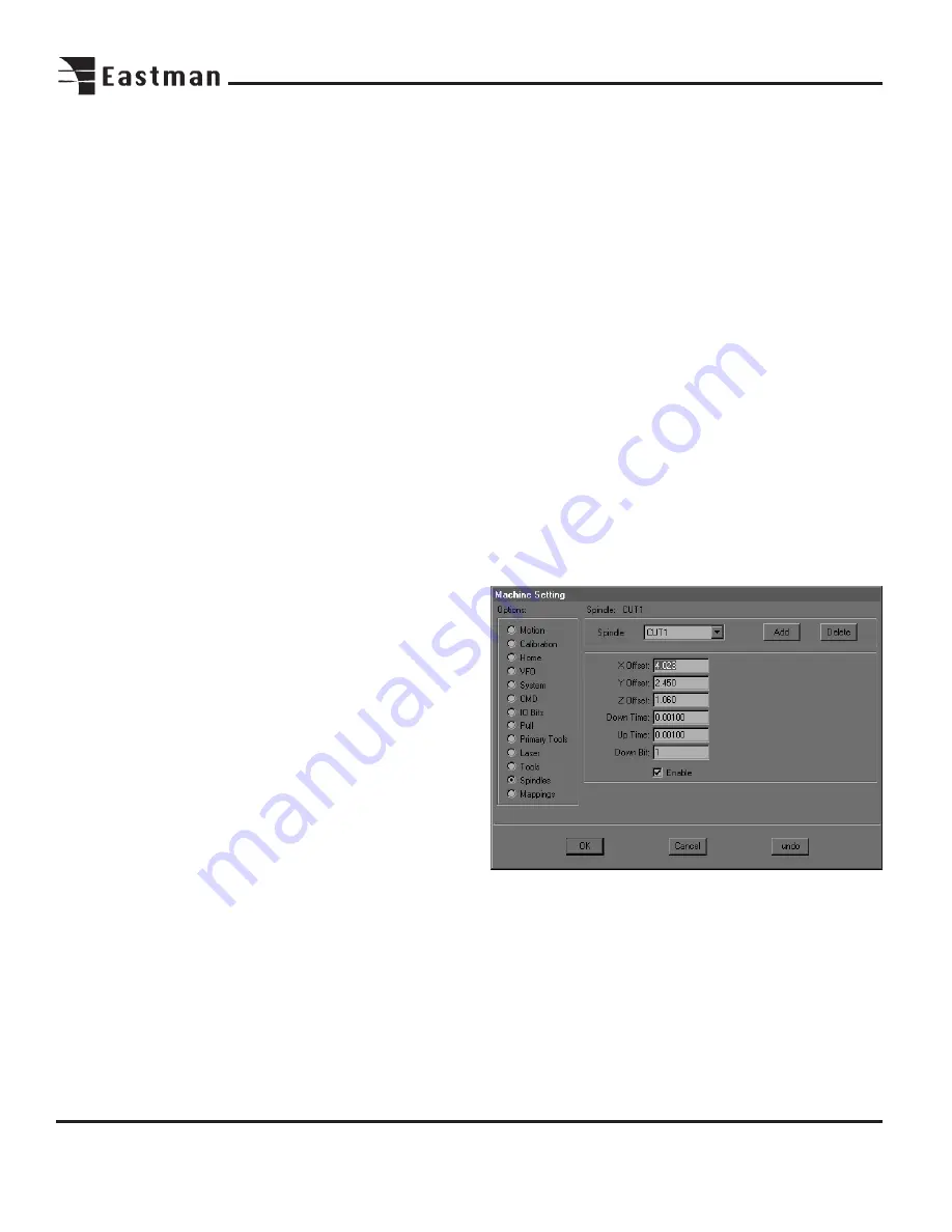
The Machine Setting Spindles screen.
Note: For detailed instructions on adjusting spindle offsets,
see the section on plotter calibration.
Spindle: Refers to the spindles, which the tools are mounted
on. On a single tool machine, select Spindle 1 (CUT1). On a
Multi-Tool machine, Spindle 1 is nearest the laser pointer.
Spindle 2 is nearest the pen holder, and Spindle 3 is directly
behind the Z axis motor.
Содержание ETS-SLS-2
Страница 1: ......
Страница 24: ...24 Notes ...
Страница 25: ...25 Notes ...
Страница 26: ...26 Notes ...
Страница 28: ......


