4
®
The Eastman
SLS 2 Stack Labeler is shipped partially
disassembled with all the necessary parts for proper setup
and operation. To get the best performance, familiarize
yourself with all the functions and adjustments of this
equipment. Before any operation can take place, it is
important that you carefully read and follow the instructions
in this manual in the same sequence in which they are
presented.
INSTALLATION
Table Preparation
The spreading table required to operate your SLS 2 Stack
Labeler must be smooth and level. A minimum clearance of
24 inches (61 cm) is required from the table surface to the
floor and a minimum 3 feet (1 m) around the machine. If
Magna or Z-Track is required, install track at this time.
To Level Table
Use carpenter’s level to check spreading table. Be espe-
cially careful to make sure table joints mate closely. Adjust
table feet as necessary to level table.
Tracking Installation
The SLS 2 Stack Labeler requires Magna Track, Z-Track or
Guide Wheels to guide the machine.
Magna Track or Z- Track Installation
Place track sections along table top, end to end, on the
operator’s side of the table as they will be mounted. Mount
the track as shown. Make sure the joints in track are even
and DO NOT align with seams in table. Be sure track is
mounted firmly to table.
Place Machine on Table
The
SLS 2 Stack Labeler weighs approx. 400 lbs. (180 Kg.)
uncrated for a 60" machine. Wooden braces are
strapped across the underside of its cross channels and
the forklift arms should be raised to those braces when
machine is lifted.
CAUTION
When placing forklift arms under cross channels, use
care not to damage tension rods or cover.
When the
SLS 2 Stack Labeler is shipped the Stop Wands,
Stop Cams, Cable Carrier Kit and Guide Wheel Assemblies
are removed and must be installed upon installation.
Place the
SLS 2 Stack Labeler on table between end
markers (marks designating left and right end of spread).
Machines equipped with grooved wheels must be placed
on the lip of Magna or Z- Track.
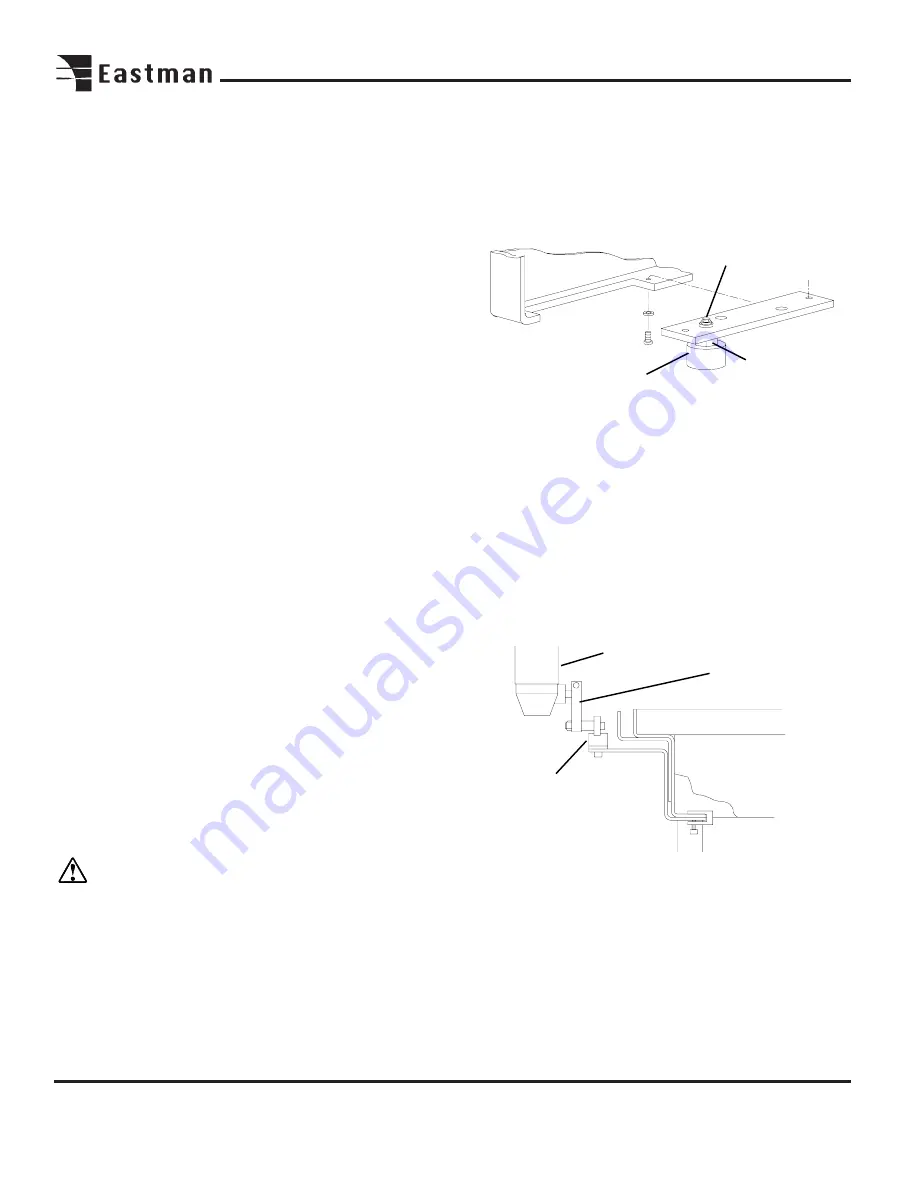
Guide Wheel
Assembly
Locking
Screw
Limit
Switch
Actuating
Arm
Safety Cam
Assembly
Guide Wheel Installation
Before installation can take place the covers must be
removed for access to the mounting holes. Remove the
mounting screws on the covers. Carefully remove the covers.
Mount the guide wheel assemblies as shown. To Adjust
Guide Wheels, Loosen the locking screw and turn the
adjusting nut until guide wheel makes contact with table. Do
not over tighten. If more adjustment is required, relocate
guide wheel in next hole. Tighten locking screw when
adjustment is complete.
Adjusting
Nut
Safety Cam & Home/Limit Switch Installation
The Safety Cams, Limit Switch, and Home Limit Switch
Assemblies should now be installed for safety. Mount the
Safety Cams as shown at each end of the spreading area.
Loosen the limit switch actuating arm and swing into posi-
tion. Secure actuating arm. Loosen the limit switch adjust-
ment plate and lower assembly to allow the actuating arm to
make contact with safety cam. If actuating arm does not
make contact with safety cam replace arm with longer arm
provided. Replace covers and secure the flat head screws.
Содержание ETS-SLS-2
Страница 1: ......
Страница 24: ...24 Notes ...
Страница 25: ...25 Notes ...
Страница 26: ...26 Notes ...
Страница 28: ......


