22
Owner’s Manual
CHIPPER SHREDDER
Get parts online at
www.GetEarthquake.com
or Call
800-345-6007
M-F 8-5 CST
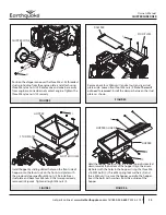
opposite side of the rotor faces outward for balanced rota-
tion. Two faces of the bolt should align in parallel with the
lock plate tabs.
NOTE: We recommend the use of high-strength thread
locker on mounting bolts.
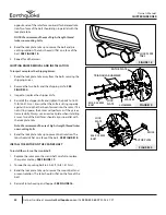
4. Bend the lock plate tabs up to secure the bolt and pre-
venting rotation. The tabs should sit flat on a face of the
bolt. SEE FIGURE 18.
5. Repeat for all hammers.
CHIPPING KNIFE REMOVAL AND INSTALLATION
To inspect or replace the chipping knives:
1. Bend the lock plate tabs away from the bolts securing the
chipping knives.
2. Remove the two bolts and the chipping knife. SEE
FIGURE 20.
3. Inspect or replace the chipper knife.
4. Reinstall the chipper knife and tighten the bolts to 18-20
ft-lb (24-27 N.m.). Ensure that the knife is sitting squarely
against the stop that has been formed into the rotor. If it is
not sitting square, the knives will perform as if they are ex-
tremely dully. Always use a new lock plate when installing
knives. Two of the bolt faces should align in parallel with
the lock plate tabs.
Note: We recommend the use of high-strength thread locker
on mounting bolts.
5. Bend the lock plate tabs up to prevent bolt rotation. The
tabs should sit flat on a face of the bolt. SEE FIGURE 18.
INSTALL THE ROTOR ON THE CRANKSHAFT
To install the rotor on the crankshaft:
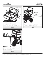
1. Replace the rotor onto the crankshaft, careful to replace
the spacer and key. SEE FIGURE 17.
2. Torque the mounting bolt to 30-35 ft-lb (41-47 N.m.).
3. Bend the lock plate tabs up to secure the mount bolt and
prevent rotation. The tabs should sit flat on the face of the
bolt.
4. Reinstall rotor housing and hopper. SEE FIGURE 16.
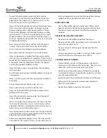
FIGURE19
FIGURE 20
TRIANGULAR-HAMMER
M10 X 50 MM
BOLT
LOCK
PLATE
J-HAMMER
ROTOR PLATE
ROTOR PLATE
KNIFE
FIGURE 18
LOCK PLATE
TABS
SPACERS
LOCK
PLATE
M8 X 16 MM
BOLT

