13
Owner’s Manual
CHIPPER SHREDDER
Get parts online at
www.GetEarthquake.com
or Call
800-345-6007
M-F 8-5 CST
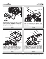
Position the chipper cone over the three M8 x1.25 threaded
studs protruding from the engine plate, and attach using
three M8 nyloc nuts (H). Rotate cone and cone base away
from engine so cone does not contact engine. Tighten the
three M8 nyloc nuts (H) securely.
FIGURE 3
CHIPPER CONE
H
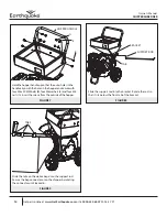
Remove back four M6 nuts (I) and set nuts and rear stud
plate aside. Loosen front four M6 nuts (I).
Note: These will
not need to removed.
Install the damper between the stud
plates as shown.
FIGURE 4
STUD PLATE
DAMPER
I
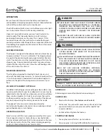
Install hopper by sliding slotted holes on the front side of
hopper onto the four studs on the front stud plate with
the previously loosened four M6 nuts (I). Reinstall rear
stud plate and back four M6 nuts (I) that were previously
removed in Figure 4. Tighten all eight M6 nuts (I).
FIGURE 5
I
HOPPER
SLOTTED HOLES
I
STUD PLATES
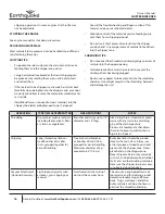
Hold the hopper guard so that the rubber guard is directed
down towards the bottom of the hopper. Align the assem-
bly holes with the holes in the hopper. Using the three M6
x 16 MM bolts (C), three M6 spring lock washers (F) and
three M6 nuts (I), secure the hopper guard to the hopper.
Insert the bolts with washers from the outside of the
hopper.
FIGURE 6
HOPPER GUARD
HOPPER
C
F
I


