background image


Isokern® MAXIMUS Linear Series 

See-Thru Gas Fireplace and Chimney System 


Installation, Operation, Maintenance and Owner’s Manual 

Isokern Models: 82L48ST, 82L72ST, 82L96ST & 82L120ST


A PRODUCT OF EARTHCORE® INDUSTRIES, LLC


IMPORTANT

: This manual contains assembly rules, installation steps and guidelines, and use and maintenance instructions 

for Isokern MAXIMUS Linear Series See-Thru gas appliances. This manual must become the property of and be reviewed by 

all current and future users of this product. It is the responsibility of the distributor, general contractor, and the installer of 

this product that the instructions in this manual are followed exactly and, further that the allowed gas log appliance used in 

this product be installed in strict accordance with the gas log manufacturer’s listing and explicit installation and operation 

instructions. 


Be Sure to Read Entire Manual Before Beginning Construction. 

Contents of this manual may change without prior notification. 


PFS Report No. F19-161 

USA: ANSI Z21.50 - 2019 

Canadian: CSA 2.22- 2019 


Issued:  February 2021 

Revision: 000 

©2020 Earthcore Industries, LLC 


THESE FIREPLACES ARE DESIGNED FOR USE WITH: 

PROPANE (LP) OR NATURAL GAS (NG), ONLY 

THIS MANUAL CAN ONLY BE REPRODUCED IN ITS ENTIRETY 


INSTALLER: Leave this manual with the appliance 

CONSUMER: Retain this manual for future reference


Do not install the Isokern MAXIMUS Linear Series 

Gas Fireplace in a manufactured home or mobile 

home or recreational vehicle.


This appliance complies with National Safety and 

is tested and listed to ANSI/CSA Z21.50 – 2019 as 

vented gas fireplaces.


Installation must conform to local codes. Check 

local codes prior to installation. In the absence of 

local codes, installation must conform with 

current National Fuel Gas Code, ANSI Z223.1.


Содержание Isokern Maximus Linear 82L48ST

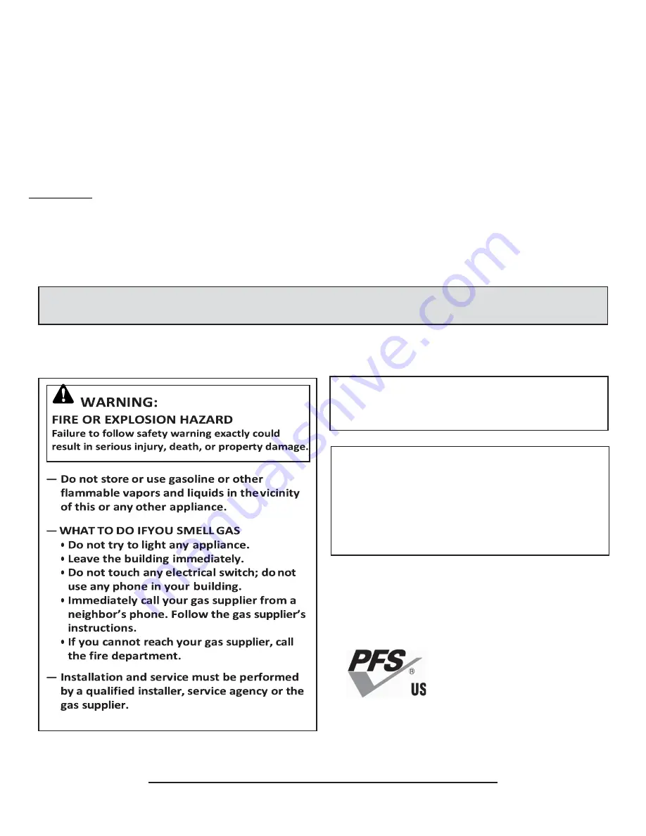
Страница 1: ...turer s listing and explicit installation and operation instructions Be Sure to Read Entire Manual Before Beginning Construction Contents of this manual may change without prior notification PFS Report No F19 161 USA ANSI Z21 50 2019 Canadian CSA 2 22 2019 Issued February 2021 Revision 000 2020 Earthcore Industries LLC THESE FIREPLACES ARE DESIGNED FOR USE WITH PROPANE LP OR NATURAL GAS NG ONLY TH...

Страница 2: ...mation 32 Enervex MFD General Information 33 Enervex RS Chimney Fan General Information 34 Enervex MFD Vertical Termination Installation 35 Enervex RS Chimney Fan Installation 36 Enervex MFD Horizontal Termination Installation 37 Chimney Fan Horizontal Termination Installation 38 Complete Electrical Schematic 39 MFD Wiring 41 Enervex RS FAN Wiring 41 Enervex ADC 100 INSTALLATION 42 Firebrick Insta...

Страница 3: ...f any component part not approved by Earthcore Industries in combination with this appliance 3 Installation or operation in a manner other than instructed in this manual 4 Burning of anything solid fuel other than the listed gas log unit and the type of gas approved for use in this gas appliance The most important areas of concern with the installation of the Isokern Maximus Linear Series See Thru...

Страница 4: ...afe operation of this fireplace WARNING This unit is not for use with solid fuel 1 Always check local building codes governing fireplaces and fireplace installations The Isokern Maximus Linear Series installation must comply with all local regional state and national codes and regulations 2 The Isokern Maximus Linear Series fireplaces are listed for use with the specific venting and burner system ...

Страница 5: ... any gas control which has been under water 19 The Isokern Maximus Linear Series is not intended to heat an entire home or to be used as a primary heat source 20 Children and adults should be alerted to the hazards of high surface temperature and should stay away from this appliance to avoid burns or clothing ignition 21 Young children should be carefully supervised when they are in the same room ...

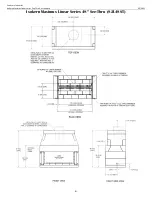
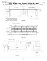
Страница 6: ...Earthcore Industries Isokern Maximus Linear Series See Thru Gas Fireplace 02 2021 6 Isokern Maximus Linear Series 48 See Thru 82L48ST ...

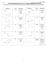
Страница 7: ... Thru Components 82L48ST Component Part Description 13 Smoke Dome 46 48 Qty 2 34 Smoke Dome Side Wall Qty 2 70 Damper Beam 46 48 Qty 2 81 Top Plate 46 48 Qty 1 Component Part Description M65A Sidewall Maximus Linear See Thru Qty 4 M93 Magnum Base Plate 48 Qty 1 M94L M94R Magnum Damper End Block Left and Right Qty 1 Each ...

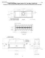
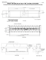
Страница 8: ...imus Linear Series See Thru Gas Fireplace 02 2021 8 Isokern Maximus Linear Series 72 See Thru 82L72ST Steel angle 6 x 6 x 1 2 cut to span firebox opening This item is not included in the components and can be sourced locally PLAN VIEW ...

Страница 9: ...luded in the components and can be sourced locally Component Part Description 16 Smoke Dome 60 72 Qty 2 18 Smoke Dome 72 Qty 2 34 Smoke Dome Side Wall Qty 2 69 Damper Beam 42 Qty 2 77A Top Plate 36 42 Qty 1 Component Part Description 83 Damper Beam 72 Qty 2 121 Top Plate 82L72 Qty 2 M65A Sidewall Maximus Linear See Thru Qty 4 M91 Magnum Base Plate 36 Qty 2 M94L M94R Magnum Damper End Block Left an...

Страница 10: ... Maximus Linear Series See Thru Gas Fireplace 02 2021 10 Isokern Maximus Linear Series 96 See Thru 82L96ST Steel angle 6 x 6 x 1 2 cut to span firebox opening This item is not included in the components and can be sourced locally ...

Страница 11: ...locally Component Part Description 16 Smoke Dome 60 72 Qty 2 17 Smoke Dome 60 Qty 2 34 Smoke Dome Side Wall Qty 2 68 Damper Beam 36 Qty 2 77A Top Plate 36 42 Qty 1 113 Smoke Dome 96 Qty 2 122 Top Plate 82L96 Qty 2 Component Part Description 191 Base Plate 84 96 108 Qty 1 167 Damper Beam 96 Qty 2 M65A Sidewall Maximus Linear See Thru Qty 1 M91 Magnum Base Plate 36 Qty 1 M93 Magnum Base Plate 48 Qty...

Страница 12: ...r Series See Thru Gas Fireplace 02 2021 12 Isokern Maximus Linear Series 120 See Thru 82L120ST Steel angle 6 x 6 x 1 2 cut to span firebox opening This item is not included in the components and can be sourced locally FRONT VIEW RIGHT SIDE VIEW ...

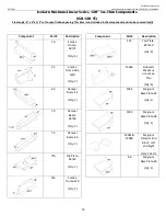
Страница 13: ...locally Component Part Description 16 Smoke Dome 60 72 Qty 4 34 Smoke Dome Side Wall Qty 2 69 Damper Beam 42 Qty 2 70 Damper Beam 46 48 Qty 2 74 Damper Beam 60 Qty 2 77A Top Plate 36 42 Qty 1 116 Smoke Dome 120 Qty 2 Component Part Description 123 Top Plate 82L120 Qty 2 M65A Sidewall Maximus Linear See Thru Qty 4 M92 Magnum Base Plate 42 Qty 1 M93 Magnum Base Plate 48 Qty 1 M94L M94R Magnum Damper...

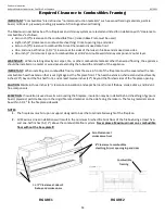
Страница 14: ...nstalling on a combustible floor system the area in front of the fireplace must be covered with a non combustible hearth extension that is set tight against the fireplace front The hearth extension shall extend at least twenty inches 20 beyond the finished front and at least twelve inches 12 beyond the finished sides of the fireplace opening CAUTION Maintain three inches 3 clearance to insulation ...

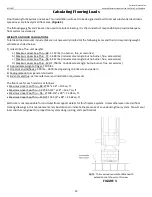
Страница 15: ...lbs includes steel angle but no burner flue accessories d Maximus Linear See Thru 120 2 756 lbs includes steel angle but no burner flue accessories 2 Approximate weight of log set 100 lbs 3 Fire brick and Adhesive 350 lbs 1800 lbs depending on brick size and pattern 4 Facing material per general contractor 5 B Vent metal flue per manufacturer and installation requirements The floor area for each m...

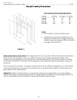
Страница 16: ...raised hearth height When calculating raised hearth height be sure to allow for the 3 thick base plate plus the 2 1 2 thick fire brick floor in addition to the height of the platform The platform shall be designed to accommodate the full weight of the firebox venting and accessories For all raised hearth construction even where concrete blocks are used to create the raised platform it is still man...

Страница 17: ...arthcore Adhesive should squeeze out along the face of the entire joint as a sign of complete and proper sealing of the joint On broader contact surfaces it is advisable to apply several additional beads of the Earthcore Adhesive to the area to assure proper sealing of the joint Proper firebox and smoke dome assembly requires approximately 100 pounds dry measure of Earthcore Adhesive LEVELING AND ...

Страница 18: ... joint as the firebox assembly progresses 1 Apply Earthcore Adhesive to the joints between each baseplate part and ensure to set each base plate in a full bed of Earthcore Adhesive on a level support surface Figure 8 See page 15 for information regarding the supporting floor system Do not set the base plate so that it is in span Refer to pages 6 13 for part and assembled firebox dimensions IMPORTA...

Страница 19: ... areas on the base plate 3 Continue assembly of the consecutive courses of the firebox side walls Apply Earthcore Adhesive to the top of each layer of side wall components before setting the next course in place Figure 10 Look for some Earthcore Adhesive to squeeze out along the joints of all contact surfaces as a sign that the joint is thoroughly sealed with the approved Earthcore Adhesive 4 When...

Страница 20: ...le iron These recesses shall begin at the front of the top sidewall components and extend 5 towards the center of the firebox These notches ensure that the angle iron is level and flush with the top of the side wall components When properly installed the angle iron will protrude beyond the front edge of the side wall components Figure 11 NOTE It is not necessary to apply Earthcore Adhesive between...

Страница 21: ... back lintel Each of the damper end blocks are designed for a specific side of the unit When properly set the vertical face of each damper end block will be flush with the outside face of the firebox side wall Figure 12 Begin by setting the rear Damper Beam components into place Next set the Damper End Blocks into place atop the sidewalls in a bed of Earthcore Adhesive Be sure to apply Earthcore A...

Страница 22: ...ng sidewall components The sloping side walls will be placed in between the front and rear smoke dome components at the ends of the firebox and are designed to rest in their notched ends Once assembled compress the smoke dome components by applying pressure to the front rear of the smoke dome assembly to force the components together Repeat this process on the opposite side of the firebox Figure 1...

Страница 23: ...ore Industries 02 2021 Isokern Maximus Linear Series See Thru Gas Fireplace 23 Assembled Maximus Linear See Thru Units Assembled 48 Maximus Linear See Thru 82L48ST Assembled 72 Maximus Linear See Thru 82L72ST ...

Страница 24: ...re Industries Isokern Maximus Linear Series See Thru Gas Fireplace 02 2021 24 Assembled Maximus Linear See Thru Units Assembled 96 Maximus Linear See Thru 82L96ST Assembled 120 Maximus Linear See Thru 82L120ST ...

Страница 25: ...hat the air kit duct be routed in the most direct path to the outside wall of the building Air kits are typically supplied with 10 duct sections It is recommended not to exceed twenty feet 20 of four inch 4 pipe If a longer length is required it is recommended that a six inch 6 diameter pipe be utilized extending up to forty feet 40 WARNING Do not use combustible duct material Avoid installing a c...

Страница 26: ...ney life Interior chimneys shall be enclosed where they extend through closets storage areas occupied spaces or anywhere the surface of the chimney could be contacted by persons or combustible materials The air space between the outer wall of the chimney and the enclosure shall not be less than 1 inches Except for installation in one or two family dwellings a factory built chimney that extends thr...

Страница 27: ...set angle of 90 Contact Earthcore representative for total distances exceeding the table minimums maximums Selecting Horizontal or Vertical Venting System With the appliance secured determine vent routing and identify the exterior termination location The following sections describe vertical roof and horizontal exterior wall vent applications Refer to the section relating to your installation Comp...

Страница 28: ...hen center anchor plate over the Isowool blanket Figure 18 3 Secure the Anchor Plate with four 4 masonry anchors 4 Starting at the anchor plate attach the first section of B Vent Pipe The B Vent sections and components use the Metal Fab positive twist lock for interconnections Align the ends of the vent push together then twist section to lock in place Figure 19 No additional fasteners are require...

Страница 29: ... to be centered in the firestop s opening When installed check to make sure the one inch 25 4 mm clearance to combustible has been maintained IMPORTANT If the area above the penetration is an attic the firestop shall be installed above the joist to prevent insulation from filling the required clearance area between the pipe and joists 7 45 Elbows are available to install the B vent chimney around ...

Страница 30: ...ns NOTE A B Vent support plate MSP is required if vertical height exceeds 30 feet Maximum of 30 feet between supports 9 The vertical vent system will be terminated with a mechanical draft system Installation instruction for the mechanical draft system begins on page 32 NOTE Vertical termination skip steps 10 11 FIGURE 21 FIGURE 22 ...

Страница 31: ...pe up to the location of termination 12 If the installation must pass through an attic floor or ceiling the B vent Firestop shall be utilized To pass the pipe through the floor ceiling begin by cutting a hole in the floor ceiling that is 2 inches larger than the outside diameter OD of the B vent pipe s outer casing The B vent Firestop is installed at the underside of this penetration The B Vent pi...

Страница 32: ...rom any authorized ENERVEX representative Accessories fans and variable frequency drives are not covered by this manual Please refer to these component s individual manuals IMPORTANT TO REDUCE THE RISK OF FIRE ELECTRICAL SHOCK OR INJURY TO PERSONS OBSERVE THE FOLLOWING 1 Use this unit in the manner intended by the manufacturer If you have questions contact the manufacturer at the address or teleph...

Страница 33: ...lve for fireplace operation The actuator has two end switches to prove damper position open or closed and is equipped with the Enerdrive fail safe system to open the damper in the event of an electrical or mechanical failure The damper is rated for temperatures up to 575 F 300 C The damper is sized to provide sufficient clearance between the damper blade and the fan inlet when open The MFD is cons...

Страница 34: ...equired by the authority having jurisdiction the installation must also conform to the Standard for Draft Equipment and The National Fuel Gas Code ANSI Z223 1 NFPA 54 All electrical wiring must be in accordance with the requirements of authority having jurisdiction or in the absence of such requirements with the National Electrical Code NFPA70 LISTINGS The Model RS is tested and listed to UL Stand...

Страница 35: ...r silicone Install a weatherproof cable connector on the side of the actuator cover to prevent water ingress to the actuator 3 Use 6 of the included sheet metal screws to secure the actuator cover to the MFD Once secure apply a bead of silicone around the seams of the cover 4 Mount the MFD outdoors at the top of the steel chimney run Slide the collar of the MFD into the steel chimney until the dam...

Страница 36: ...ed Fan Installation Vertical Termination 5 Measure the inside diameter of the flue and cut a corresponding hole in the center of the fiber mat If the flue is so big that the throat in the adapter has been reduced to fit the throat of the fan the hole in the fiber mat should correspond to the throat 6 The aluminum foil on the fiber mat must face upward against fan base 7 The chimney fan is now read...

Страница 37: ...ator cover to prevent water ingress to the actuator 3 Use 6 of the included sheet metal screws to secure the actuator cover to the MFD Once secure apply a bead of silicone around the seams of the cover 4 Mount the MFD outdoors at the end of a steel chimney Slide the collar of the MFD into the steel chimney until the damper rests on the stop flange Sheet metal screws may be installed around the col...

Страница 38: ...t to the structure that is within 10 ft 3 m of the termination point Exception This requirement shall not apply to the separation distance between the circulating air inlet and the vent discharge of a listed outdoor appliance NOTE The flue gas outlet of this appliance shall terminate at least 4 ft 1 2 m below 4 ft 1 2 m horizontally from or 1 ft 0 3 m above any door window or gravity air inlet of ...

Страница 39: ...Earthcore Industries 02 2021 Isokern Maximus Linear Series See Thru Gas Fireplace 39 Complete Electrical Schematic FIGURE 35 ...

Страница 40: ...the roof or in a horizontal mount on an outside wall Junction capacitor box will be mounted near the fan mount Fan circuit disconnect de energizes the fan circuit for the purpose of servicing recommended installed by the manufacturer must meet local code requirements not supplied Fan speed control switch is installed for the purpose of fan speed initial set up should be mounted in a location that ...

Страница 41: ...iring must be in compliance with the local codes or in their absence with the National Electric Code NFPA 70 latest edition If an external electrical source is utilized system must be electrically grounded in accordance with requirements of the authority having jurisdiction or in the absence of such requirements with the National Electrical Code NFPA 70 latest edition Power requirements for the sy...

Страница 42: ...witch PDS must be used with the ADC100 control as a system safety device The PDS monitors the pressure inside the stack and signals the control to shut down the appliance if insufficient draft exists A stack probe senses the pressure read by the PDS and is connected via silicone tubing The silicone tubing supplied with the PDS should be connected to the NEGATIVE port of the PDS This is the bottom ...

Страница 43: ... installed close to the fan inlet See Figure 43 7 To produce an accurate pressure reading the probe should be installed flush with the inner wall of the chimney or stack If double walled stack is used the probe should be flush with the inner most wall Fan Speed Control 8 Locate the FSC in close proximity to the burner valve control system but only in a location accessible to service technician Con...

Страница 44: ...trol system Terminal Description Terminal Description 1 Line Power L1 11 Proven Draft Switch NO white 2 Line Neutral 12 Proven Draft Switch NC gray 3 Ground 13 Proven Draft Switch C purple 4 Fan Power to FSC 14 Line Power L1 from junction box 5 Fan Neutral 15 Damper Power cord L 6 Fan Ground 16 Damper actuator cord S1 NC purple 7 Wall Switch 17 Damper actuator cord S3 NO white 8 Jumper to terminal...

Страница 45: ...plied Approximately 35 to 40 lbs of prepared mortar will lay up one hundred 9 x 4 x 2 straights IMPORTANT DO NOT add additives such as fire clay sand cement or other accelerators These instructions may vary because of different climates and conditions The use of good masonry practices for your area should also be considered INSTALLATION INSTRUCTIONS 1 Wet mop the inside of the fireplace with a dam...

Страница 46: ...nsion 2 Repeat Step 1 for the opposite side of See Thru firebox 3 Starting at the front edge of the unit s sidewall apply split firebrick to the side wall of the unit Ensure approximately gap is kept between firebrick and damper beam damper block assembly to allow for expansion 4 Repeat on opposite side wall IMPORTANT Ensure that the required holes for the Isoflames Linear burner s 3 8 gas supply ...

Страница 47: ...setting the noncombustible facing material onto the drywall that spans across the top of the firebox opening there will be a gap between the back of the noncombustible finish material and the rough front face of the Isokern firebox Be sure to fill this gap with Earthcore Adhesive in conjunction with placement of the code required noncombustible finish facing material that is set across the top of ...

Страница 48: ... that create the room wall finish All combustible trim projecting less than one and one half inch 1 1 2 from this plane must be kept a minimum of eight inches 8 from the sides top of the firebox openings All combustible trim projecting more than one and one half inch 1 1 2 must be kept a minimum of twelve inches 12 from the fireplace opening Parts of the combustible mantle assembly located along t...

Страница 49: ... of 1 2 psi 3 5 kPa The appliance must be isolated from the gas piping system by closing its equipment shutoff valve during any pressure testing of the supply piping system at test pressures equal to or less than 1 2 psi 3 5 kPa 8 Do not use this appliance if any part has been under water Immediately call a qualified service technician to inspect the appliance and to replace any part of the contro...

Страница 50: ...y sort may void manufacturer s warranty listings and approvals 25 The ISOFLAMES Linear Burner system is not intended to heat an entire home or to be used as a primary heat source 26 Children and adults should be alerted to the hazards of high surface temperature and should stay away from this appliance to avoid burns or clothing ignition 27 Young children should be carefully supervised when they a...

Страница 51: ...even though no odor exists Carbon Monoxide Poisoning Early signs of carbon monoxide poisoning resemble flu symptoms including headaches dizziness or nausea If you have these signs the fireplace may not have been installed properly get fresh air at once Have the fireplace inspected and serviced by a qualified service person or your gas supplier Some people are more affected by carbon monoxide than ...

Страница 52: ...ner Assembly propane ISF E 36 60 72 96N ISF E 36 60 72 96P 1 1 2 Pilot Assembly natural gas Pilot Assembly propane ISF E PAN ISF E PAP 1 1 3 Gas Valve natural gas Gas Valve propane ISF E GVN ISF E GVP 1 1 4 Control module remote receiver ISF E CM 1 5 Battery Holder Switch ISF E BH 1 6 Remote Transmitter ISF E RM 1 7 1 2 Flared fitting female adapter ISF E FFA1 1 8 3 8 Flared fitting female adapter...

Страница 53: ...pecifications Burner Specifications Burner Model Minimum Fireplace Dimension in BTU Depth Height Width Nat Gas L P Gas Front Rear High Low High Low ISF36LB 17 5 16 48 37 54K 38K 48K 36K ISF60LB 17 5 16 72 61 90K 63K 80K 60K ISF72LB 17 5 16 84 73 108K 75K 96K 72K ISF96LB 17 5 16 108 97 110K 84K 105K 87K TABLE 3 ...

Страница 54: ... off gas and electricity before starting installation or service 5 Make sure gas piping is pressure tested before control is connected High pressure can damage the control causing a hazardous condition 6 Make sure piping is clean and free from burrs Apply a small amount of good quality gas rated pipe thread compound or plumbers tape suitable for the gas being used Thread compound should be used sp...

Страница 55: ... kPa The appliance when installed must be electrically grounded in accordance with local codes or in the absence of local codes with the National Electrical Code ANSI NFPA 70 If not installed and maintained in accordance with the manufacturer s instructions this product could expose you to substances in fuel or fuel combustion which are known to the state of California to cause cancer birth defect...

Страница 56: ...portion of this manual pgs 45 46 3 The burner cavity must have a height of 2 1 2 a depth of 9 1 4 and the length shall extend the entire width of firebox Table 5 4 The 48 and 72 Maximus Linear See Thru fireplaces 82L48ST 82L72ST will require the ISF36 60LB respectively Gas supply piping for these models shall terminate not less than 3 from sidewall Figure 56 57 58 5 The 96 and 120 Maximus Linear S...

Страница 57: ...nector to the gas inlet flared fitting on the burner assembly 7 Connect the other end of 12 flex connector to the gas supply 8 Avoid creating kinks in the flex connector 9 Make sure all connections are tightly secured 10 Before replacing the removed burner top from step 4 locate the perforated rectangular section in the pan Gently remove this section along the perforations using a screwdriver or p...

Страница 58: ...eplace 02 2021 58 36 Burner Connection ISF36LB For Isokern Maximus Linear 82L48ST 60 Burner Connection ISF60LB For Isokern Maximus Linear 82L72ST ISF36LB Box No Part No Qty 4 E 18BP4 1 8 E 12BP1 1 ISF60LB Box No Part No Qty 1 E 18BP1 1 4 E 18BP4 1 6 E 18BP6 1 4 6 1 4 8 ...

Страница 59: ... 2021 Isokern Maximus Linear Series See Thru Gas Fireplace 59 72 Burner Connection ISF72LB For Isokern Maximus Linear 82L96ST ISF72LB Box No Part No Qty 4 E 18BP4 1 5 E 18BP5 1 9 E 12BP2 1 10 E 12BP3 1 13 E BPC 1 5 10 13 9 4 ...

Страница 60: ...near Series See Thru Gas Fireplace 02 2021 60 96 Burner Connection ISF96LB For Isokern Maximus Linear 82L120ST ISF96LB Box No Part No Qty 2 E 18BP2 1 3 E 18BP3 1 9 E 12BP2 1 10 E 12BP3 1 11 E 12BP4 1 12 E 12BP5 1 13 E BPC 1 13 3 10 12 9 2 11 ...

Страница 61: ... than air and will settle on the floor WHAT TO DO IFYOU SMELL GAS Do not try to light any appliance Do not touch any electric switch do not use any phone in your building Immediately call your gas supplier from a neighbor s phone Follow the gas supplier s instructions If you cannot reach your gas supplier call the fire department C If any portion of this appliance does not operate as the instructi...

Страница 62: ...o the battery bay in the transmitter Correctly align polarity 2 Insert the four 4 provided AA batteries into the wall switch battery bay behind the wall switch plate Correctly align polarity 3 On the wall switch place the three position slider switch in the REMOTE position 4 On the wall switch front cover insert the end of a paper clip or other similar object into the hole marked PRG NOTE The Rece...

Страница 63: ... appliance pressing the Down Arrow Key once will reduce the flame height by one step until the flame is turned off The Up Arrow Key will increase the flame height each time it is pressed If the Up Arrow Key is pressed while the system is on but the flame is off the flame will come on in the high position Figure 64 A single beep will confirm reception of the command FLAME COLOR AND BEHAVIOR This ap...

Страница 64: ...everal cycles to purge out all the air in pilot tube 7 Once the pilot is ignited the main burner valve will turn on within 7 seconds 8 The burner should ignite and the flames should travel along the length of the burner 9 Initially the flames will have a bluish appearance and will gradually become more yellow as appliance heats up 10 After a few minutes shut off burner and de energize full system ...

Страница 65: ... in pilot gas line It may take a few minutes to purge out all the air from the pilot gas tube to ignite No gas Verify pilot gas tube is threaded sufficiently to gas valve Verify all gas connections going to and from gas valve are tight Verify main gas shutoff valve is in ON position Pilot won t stay ignited Flame sensor obstruction Remove any obstruction near pilot igniter and flame sensor Loose p...

Страница 66: ...prove go into alarm for 30 seconds followed by a full retry Flashes 3 If PDS loses proof for 15 seconds after initial PDS prove AUX OUT de energize stay in alarm until PDS prove returns and AUX OUT will re energize Flashes 4 If at any point after AUX OUT proves the damper prove is removed the board immediately goes into alarm for 30 seconds followed by a full retry Flashes 5 must have sw3 on if PD...

Страница 67: ...FLECTIVE VESPER BLACK FIRE GLASS 10 LB JAR RFG 10 KD 1 2 REFLECTIVE KRYSTALLO DIAMOND FIRE GLASS 10 LB JAR RFG 10 AD 1 2 REFLECTIVE AMBER DIAMOND FIRE GLASS 10 LB JAR Glass Media will be included with the Isoflames Linear Burner for each Maximus Linear Unit A color selection will need to be chosen when ordering your fireplace unit The following designated amount will be included for each size 82L4...

Страница 68: ...Earthcore Industries Isokern Maximus Linear Series See Thru Gas Fireplace 02 2021 68 ...

Страница 69: ...is warranty the party to whom this warranty is extended shall notify ISOKERN 6899 Phillips Industrial Blvd Jacksonville Florida 32256 in writing by registered mail within thirty 30 days following the discovery of the defect within the lifetime warranty period The notice shall contain 1 the date of purchase 2 place of purchase 3 address of installation 4 name address and phone number of the owner a...

Отзывы: