53
8.3.3 I/O properties
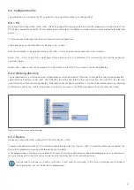
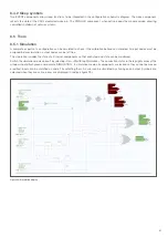
All I/O property information can be seen in the schematic diagram above the component. These include the CAN address and
byte number for soft I/Os.
8.3.3.1 Input properties
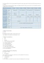
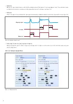
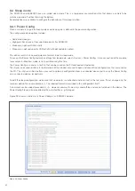
Figure 19 shows the window for setting the input properties. The configuration options are described in more detail below.
Figure 19: Input properties
• Input#
Assignment of a physical input or a soft input (CAN). CAN inputs are set up under »Cal«, »Communications«.
• Name
Enter a name that is displayed in the schematic diagram display.
• Pull up / Pull down (only for physical inputs)
Determines whether the input is in the high or low state when no input signal is present.
• Alarm on timeout / Default on timeout (only for soft inputs)
Selection between triggering an alarm or switching to the default state when the timeout of the CAN message has expired.
• Default state ON / OFF (only for soft inputs)
Set the default value of the input if »Default on Timeout« is selected.
• Msg timeout (only for soft inputs)
Set the maximum amount of time that may elapse between two CAN input messages before a timeout alarm is triggered.
• Analogue
Definition of the input as an analogue input
• High threshold
Input of the upper voltage level from which the input is evaluated as high (for internal further processing as a digital signal).
• Low threshold
Input of the upper voltage level from which the input is evaluated as low (for internal further processing as a digital signal).


