18
6. CIRCUIT BREAKER
FUNCTIONALITY
The last third of the overview page displays addi-
tional information and functions for the selected cir-
cuit breaker. Three different tabs can be selected on
the left-hand side. These are explained below:
6.1 Parameter
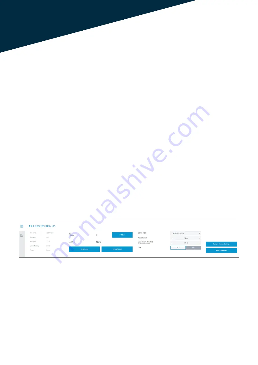
The first tab displays general information about the
circuit breaker, such as the serial number and the
hardware and software version. Furthermore, the last
error reason can be read out.
The possible parameters that can be set have al-
ready been explained in the "Batch Edit De-vice"
function. The different input fields can be adjusted by
the integrated arrow keys. If the required value is
reached, the new setting can be loaded into the de-
vice via the "Write Parameter" button.
The "Restore Factory Settings" button resets all pa-
rameters to the factory settings.
The "Lock" selection option blocks switching the cir-
cuit breaker off or on from the software.
As soon as the function is set to status "OFF", the cir-
cuit breaker can be switched. As soon as the circuit
breaker is switched off from the software, the hard-
ware LED at the channel shows the colour orange.
Attention:
The role of the logged in account has to be checked.
The differences between the Admin and the User
mode are explained in chapter 4.1.3.4.
In addition, the function for resetting a circuit breaker
and switching it on and off is not available with a con-
nected fieldbus interface. The PLC software has a
higher priority.
Furthermore, control and writing via the webserver
can be deactivated via the PLC software (Configura-
tion data of the CPC12 - Byte 0 Bit 0)!
Image 25: General information and adjustable parameters of the circuit breaker


