background image

24

E-flite S.E.5a Slow Flyer ARF Assembly Manual


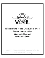
5. The rigging then will go from the front lower hole to 

the upper rear hole, crossing the outer strut.


6. Route the rigging from the outer strut to the rear 

hole in the fuselage. This is where having a needle or 

hardening the rigging will come in quite handy.


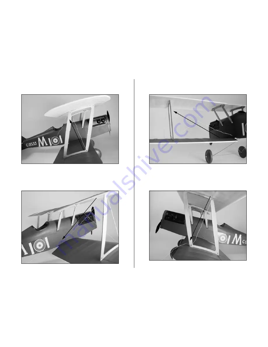
7. The rigging then goes from the fuselage to the upper 

rear hole in the outer strut.


8. Cross the rigging from the rear upper hole back  

down the front lower hole where this section of rigging 

was started.

Содержание S.E.5a Slow Flyer ARF EFL1925

Страница 1: ...ingspan 30 in 760mm Length 23 in 595mm Wing Area 310 sq in 20 0 sq dm Weight w battery 7 5 8 5 oz 210 225 g Weight w o battery 7 oz 200 g Radio 3 channels with 2 sub micro servos S E 5a Slow Flyer ARF...

Страница 2: ...tions to help make assembly easier to understand and to provide breaks between each major section In addition check boxes have been placed next to each step to keep track of each step completed Steps...

Страница 3: ...free Spektrum DX6i 2 4GHz DSM2 6 channel full range transmitter and receiver no servos If using your own transmitter or any other we recommend the E flite S60 super sub micro servos If you own the Sp...

Страница 4: ...0 Park Flyer Tool Assortment 5 piece Or Purchase Separately EFLA257 Screwdriver 0 Phillips or included with EFLA250 Hobby knife Felt tipped pen Square Sandpaper Pin drill Drill Bit 1 16 in 1 5mm Plier...

Страница 5: ...allation operation maintenance or attempted repair by anyone other than Horizon Return of any goods by Purchaser must be approved in writing by Horizon before shipment Damage Limits HORIZON SHALL NOT...

Страница 6: ...the shipping carton Warranty Inspection and Repairs To receive warranty service you must include your original sales receipt verifying the proof of purchase date Provided warranty conditions have been...

Страница 7: ...operating your model in the street where injury or damage can occur Never operate the model out into the street or populated areas for any reason Never operate your model with low transmitter batterie...

Страница 8: ...ute the wires for the motor battery and servo connections as shown 3 Locate the 11 2 inch 38mm motor tube Follow the instructions included with the motor to glue using RTV silicone the motor to the mo...

Страница 9: ...motor together at this time Important Information About Your Propeller It is very important to check to be sure the propeller is balanced before installing onto the shaft An unbalanced propeller may...

Страница 10: ...he motor box and motor tube Apply CA to the tube at both the front and rear of the motor box 8 Use a pin drill and 1 16 inch 1 5mm drill bit to enlarge the outer hole in the servo arm Slide the micro...

Страница 11: ...the servos into the radio system and make sure all servos operate and are centered as well 12 Install the servo arms on the rudder and elevator servos prior to installation The servos will have the a...

Страница 12: ...tape to secure the receiver inside the fuselage Position the antenna wires according to your radio manual Never shorten the receiver antenna wire as this will greatly reduce the range of your radio sy...

Страница 13: ...make corrections to the direction of rotation of the motor if necessary Note If the motor rubs on the cowl enlarge the hole in the cowl for the motor so the motor does not rub the cowl Wing Installati...

Страница 14: ...ing mounting screws at this time mmm 3 Use a pin drill and 1 16 inch 1 5mm drill bit to drill a hole for the wing mounting screw marked in the previous step mmm 4 Use a 2 x 5 8 inch sheet metal screw...

Страница 15: ...r repeat Steps 2 through 4 to install the remaining three 2 x 5 8 inch sheet metal screws that hold the bottom wing to the fuselage 7 The installation of the top wing is identical to that of the botto...

Страница 16: ...p and bottom wings Attach the Fin and Stabilizer Required Parts Rudder Fin Elevator Stabilizer Micro control horn 2 Micro control horn backplate 2 Required Tools and Adhesives Square Foam safe CA Sand...

Страница 17: ...t in the elevator for the elevator control horn 3 Slide the micro control horn backplate onto the control horn from the opposite side of the elevator as the horn Apply a few drops of foam safe CA onto...

Страница 18: ...ge where the tail rests to correct any alignment problems Use foam safe CA to glue the tail to the fuselage once the tail is aligned to the wings Radio Installation Required Parts Assembled fuselage 2...

Страница 19: ...tor control horn m 3 The pushrod wire will exit the pushrod tube inside the fuselage and then pass through the connector on the servo 4 Slide the elevator pushrod wire through the center hole in the c...

Страница 20: ...e screw in the connector and a 0 Phillips screwdriver to secure the elevator pushrod to the connector Use side cutters to remove any excess pushrod wire that may interfere with the operation of the el...

Страница 21: ...eel onto the axle Use a wheel retainer to secure the wheel Hint Use medium foam safe CA on the retainer if it is not snug on the axle Use care not to glue the wheel to the axle 2 Slide the front of th...

Страница 22: ...le Hobby knife Note Installing the rigging will add to the appearance and strength of your airplane but you will not be able to remove the wings without cutting the rigging The rigging is required on...

Страница 23: ...am safe CA to glue the rigging to the strut but don t fully cover the hole with CA as the rigging will eventually pass back through the hole Allow the CA to fully cure before proceeding 2 The rigging...

Страница 24: ...oute the rigging from the outer strut to the rear hole in the fuselage This is where having a needle or hardening the rigging will come in quite handy 7 The rigging then goes from the fuselage to the...

Страница 25: ...ave not built a warp into the wings during this process A quick sight from the front will verify there are not warps 10 Using a hobby knife trim off the remaining thread once the CA has fully cured 11...

Страница 26: ...en the cabane struts 14 The rigging is then routed to the lower rear of the outer strut as shown 15 Next route the rigging from the lower rear hole to the upper front hole in the outer strut 16 Run th...

Страница 27: ...safe CA to glue the end of the rigging in position once the rigging has been tensioned Once again take a look and ensure there are no warps in the two wings Using a hobby knife trim off the remaining...

Страница 28: ...in the top wing Control Throws 1 Turn on the transmitter and receiver of your aircraft Check the movement of the rudder using the transmitter When the stick is moved right the rudder should also move...

Страница 29: ...ure to range check your radio This is accomplished by turning on your transmitter with the antenna collapsed Turn on the receiver in your airplane With your airplane on the ground and the engine runni...

Страница 30: ...eck all the control horns servo horns and clevises to make sure they are secure and in good condition Replace any items that would be considered questionable Failure of any of these components in flig...

Страница 31: ...be established in front of which all flying takes place with the other side for spectators Only personnel involved with flying the aircraft are allowed at or in front of the flight line Intentional f...

Страница 32: ...11036 2007 Horizon Hobby Inc 4105 Fieldstone Road Champaign Illinois 61822 877 504 0233 horizonhobby com E fliteRC com...

Отзывы: