User Manual HTS801
Humidity and Temperature Sensor for High Humidity and Chemically Polluted Conditions | 36
5.2
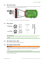
With Cable Glands
For cabling via the cable glands and direct electrical connection within the enclosure, the assignment of the screw
terminals in the lower part of the enclosure is as shown in Fig. 33.
V+
GND
GND
OUT 1
OUT 2
GND RS485
RS485 A (=D+)
RS485 B (=D-)
V
mA
8 - 35 V DC
12 - 30 V AC
1
2
3
4
5
6
7
8
Modbus RTU
(galvanically isolated)
Analogue outputs
Supply
V
mA
Fig. 33 Pin assignment on screw terminals for electrical connection via cable glands
5.3
Plug Options
1
2
3
4
5
Description:
Pin assignment:
V+ 1
OUT1 2
GND (Supply)
3
OUT2 4
GND (OUT)
5
Description:
Pin assignment:
Not assigned
1
RS485 B (D-)
2
Not assigned
3
RS485 A (D+)
4
RS485 GND
5
Front view on device
Plug for supply and
analogue output
Socket for
RS485 connection
E4
E6
Front view on device
PLEASE NOTE
The cable(s) should be connected according to the number stamped in the plug as shown in the above
drawings.
5.4
ARC Module (Option AM1)
Please refer to chapter 3.5.3. ARC Module (Option AM1).
5.5
Alarm Module (Option AM2)
WARNING
If the stainless steel enclosure is equipped with an alarm module (option AM2) or an integrated power supply
100 - 240 V AC (option AM3) and installation is not carried out correctly, there is the danger of a touch
voltage.
The HTS801’s stainless steel enclosure must therefore be grounded during operation.
For the contact scheme in standard and inverted operation mode, please refer to Tab. 4 in chapter 5.1 Electrical
Содержание HTS801
Страница 61: ...User Manual HTS801 Humidity and Temperature Sensor for High Humidity and Chemically Polluted Conditions 61...
Страница 62: ...User Manual HTS801 Humidity and Temperature Sensor for High Humidity and Chemically Polluted Conditions 62...
Страница 63: ...User Manual HTS801 Humidity and Temperature Sensor for High Humidity and Chemically Polluted Conditions 63...


