background image

User Manual HTS801 

Humidity and Temperature Sensor for High Humidity and Chemically Polluted Conditions  |  35

Option

Polycarbonate Enclosure

Stainless Steel Enclosure

Pin Assignment

AM3

Option E4

Power  

analogue output

1

2

3

4

5

GND

GND Output

OUT 2

V+

OUT 1

Option E5

Modbus RTU

M16x1.5

Option E6

Modbus RTU Power  

analogue output

Option E12

Modbus RTU

Power  

analogue output

Option AM3

1

2

3

4

5

GND

GND Output

OUT 2

V+

OUT 1

Power analogue output

Analogue 

output

Modbus RTU

(only with order code J3)

Power supply

neutral wire
(N)

grounding
(PE)

phase

(L1)

Power supply 100 - 240 V AC

for stainless steel enclosure

Plug

2

1

4

3

5

RS485 B 
(=D-)

GND RS485 
(shielded)

RS485 A 

(=D+)

n.c.

Modbus RTU 

n.c.

2

1

4

3

5

RS485 B 
(=D-)

GND RS485 
(shielded)

RS485 A 

(=D+)

n.c.

n.c.

2

1

4

3

5

RS485 B 
(=D-)

GND RS485 
(shielded)

RS485 A 

(=D+)

n.c.

Modbus RTU

Socket 

n.c.

Standard

2x M16x1.5

Option J4

V+

GND
GND

OUT 1
OUT 2

GND RS485

RS485 A (=D+)

RS485 B (=D-)

1

2
3
4
5
6
7

8

6

4

5

3

1

2

NO

NC

C

Standard operation mode

REL 1

NO

NC

C

REL 2

RELA

Y 2

RELA

Y 1

Option AM2

NC

6

NO

4

C

5

NC

3

NO

1

C

2

Inverted operation mode

RELA

Y 2

RELA

Y 1

2x M16x1.5

Ethernet 

Modbus TCP

1

2

3

4

5

n.c.

GND Output

OUT 2

n.c.

OUT 1

Analogue output

Plug

1

3

neutral wire
(N)

n.c.

phase

(L1)

n.c.

Power supply 100 - 240 V AC

for polycarbonate enclosure

Plug

Plug

Socket

Standard

Option E4

Option E5

Option AM3

Power

analogue output

Power

analogue output

1 x M16x1.5 mounted

1 x M16x1.5 enclosed

M16x1.5 

Modbus RTU

Modbus RTU

Analogue output

Modbus RTU

(only with 

order code J3)

Power supply

100 - 240 V AC

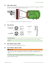
EE310/EE360 - Electrical connection for stainless steel housing (HS2)

Option E6

Option AM2

2x M16x1.5

Option E4

Power  

analogue output

1

2

3

4

5

GND

GND Output

OUT 2

V+

OUT 1

Option E5

Modbus RTU

M16x1.5

Option E6

Modbus RTU Power  

analogue output

Option E12

Modbus RTU

Power  

analogue output

Option AM3

1

2

3

4

5

GND

GND Output

OUT 2

V+

OUT 1

Power analogue output

Analogue 

output

Modbus RTU

(only with order code J3)

Power supply

neutral wire
(N)

grounding
(PE)

phase

(L1)

Power supply 100 - 240 V AC

for stainless steel enclosure

Plug

2

1

4

3

5

RS485 B 
(=D-)

GND RS485 
(shielded)

RS485 A 

(=D+)

n.c.

Modbus RTU 

n.c.

2

1

4

3

5

RS485 B 
(=D-)

GND RS485 
(shielded)

RS485 A 

(=D+)

n.c.

n.c.

2

1

4

3

5

RS485 B 
(=D-)

GND RS485 
(shielded)

RS485 A 

(=D+)

n.c.

Modbus RTU

Socket 

n.c.

Standard

2x M16x1.5

Option J4

V+

GND
GND

OUT 1
OUT 2

GND RS485

RS485 A (=D+)

RS485 B (=D-)

1

2
3
4
5
6
7

8

6

4

5

3

1

2

NO

NC

C

Standard operation mode

REL 1

NO

NC

C

REL 2

RELA

Y 2

RELA

Y 1

Option AM2

NC

6

NO

4

C

5

NC

3

NO

1

C

2

Inverted operation mode

RELA

Y 2

RELA

Y 1

2x M16x1.5

Ethernet 

Modbus TCP

1

2

3

4

5

n.c.

GND Output

OUT 2

n.c.

OUT 1

Analogue output

Plug

1

3

neutral wire
(N)

n.c.

phase

(L1)

n.c.

Power supply 100 - 240 V AC

for polycarbonate enclosure

Plug

Plug

Socket

Tab. 4 

Various options for electrical connections and wiring

Содержание HTS801

Страница 1: ...User Manual Humidity and Temperature Sensor for High Humidity and Chemically Polluted Conditions HTS801...

Страница 2: ...13 3 5 2 rapidX Smart Probe Option PC7 15 3 5 3 ARC Module Option AM1 16 3 5 4 Alarm Module Option AM2 17 3 5 5 Integrated Power Supply 100 240 V AC Option AM3 19 3 5 6 RS485 Module Modbus RTU Option...

Страница 3: ...r Messages 46 7 1 1 Error Messages on the Display 46 7 1 2 Status and Error Messages via LEDs 46 7 2 Cleaning the Sensing Head and Filter Cap Replacement 47 7 3 Automatic ReCovery ARC 47 7 4 RH and T...

Страница 4: ...ng PLEASE NOTE Find this document and further product information on our website at www epluse com hts801 1 1 Explanation of Warning Notices and Symbols Safety precautions Precautionary statements war...

Страница 5: ...imes in the back section of the enclosure The HTS801 enclosure must be tightly closed during operation An open enclosure corresponds to IP00 and exposes components carrying dangerous voltage Any work...

Страница 6: ...specifically described in this manual NOTICE Failing to follow the instructions in this user manual may lead to measurement inaccuracy and device failures The HTS801 may only be operated under the co...

Страница 7: ...l be removed from the process Service operations other than described in this user manual may only be performed by the manufacturer 1 3 Environmental Aspects PLEASE NOTE Products from E E Elektronik G...

Страница 8: ...ondensation or chemical contamination In addition it is perfectly protected by the E E proprietary coating Different heating modes of the monolithic RH and T sensing element allow for best adaption to...

Страница 9: ...iew 3 3 Configuration Interface The HTS801 is ready to use and does not require any configuration by the user The factory setup of HTS801 corresponds to the type number ordered Please refer to the dat...

Страница 10: ...and 90 RH in steps of 20 RH and 20 min stabilisation time The start of the ARC function can be triggered as follows Manual by using PCS10 or via display and push buttons A manual start of the ARC func...

Страница 11: ...outputs are frozen In other words the measuring values at the outputs are kept constant during the ARC cycle The orange LED D5 at the main PCB near the USB interface is permanently lit during the ARC...

Страница 12: ...ng the complete heating and cool down process the values on the outputs are frozen In other words the measuring values at the analog outputs are kept constant during the CG cycle The following HTS801...

Страница 13: ...ated dew point The relative humidity near condensation is determined with the T value of an additional T sensor of Type T17 T28 The following HTS801 types incorporate the dual heating system T17 with...

Страница 14: ...Control panel with display and push buttons Data Logging The TFT display with the integrated data logging function saves all measured and calculated values to the internal memory The data logger has a...

Страница 15: ...e is violated a buzzer sounds periodically This buzzer can be switched off or on here Factory default is on Error Indication As soon as an error occurs an indication shows the error code 3 5 2 rapidX...

Страница 16: ...tart the ARC heating function with external signal Fig 14 ARC module in polycarbonate enclosure During the ARC process the orange LED 5 at the main PCB near the USB interface is permanently lit refer...

Страница 17: ...chapter 11 3 Optional Menus Fig 55 Alarm output Switch Hysteresis Mode The switching behavior is determined by entering a switching point and an associated hysteresis value t closed open closed open N...

Страница 18: ...Indication Mode When error indication mode is selected various errors will trigger the alarm output t closed open Error occurs No error Terminal 5 6 Normal state Inverted Fig 19 Example of error mode...

Страница 19: ...oder low voltage 3 5 5 Integrated Power Supply 100 240 V AC Option AM3 This module allows the HTS801 to be powered with 100 240 V AC 50 60 Hz 2 VA Polycarbonate enclosure Stainless steel enclosure Fig...

Страница 20: ...ory settings User selectable values via PCS10 Baud rate 9 600 9 600 19 200 38 400 57 600 76 800 Data bits 8 8 Parity Even None odd even Stop bits 1 1 2 Modbus address 230 0xE6 1 247 Tab 2 Modbus RTU p...

Страница 21: ...s Factory settings IP Address 192 168 0 64 Subnet Mask 255 255 255 0 Gateway 192 168 0 1 DNS 192 168 0 1 Tab 3 IPV4 settings DHCP options can be set with jumper on the electronics board refer to Fig 2...

Страница 22: ...p to 180 C 356 F Type T7 Probe Pressure tight up to 20 bar 300 psi for Td measurement code probe length 1 code cable length 1 12 0 47 15 0 60 code cable length 1 code probe length 1 12 0 5 G1 2 ISO OR...

Страница 23: ...de cable length 1 150 5 9 6 0 24 1 2 ISO or 1 2 NPT T 6 0 24 T 24 0 94 code cable length 1 150 5 9 35 1 38 4 Mounting and Installation 4 1 Sensor Enclosure Mounting with Screws Drill the mounting hole...

Страница 24: ...utside the process on the cable side PLEASE NOTE The sensing probe must be mounted horizontally or vertically pointing downwards If possible a drip sheet should be fitted for each mounting PLEASE NOTE...

Страница 25: ...ounting flange HA010201 Fig 28 Mounting the remote probe of HTS801 T5 The stainless steel mounting flange is not appropriate for pressure tight mounting For pressure tight requirements use HTS801 T10...

Страница 26: ...Bending over the sensing probe should be avoided under any circumstances Make sure that the surface of the probe is not damaged during installation A damaged probe surface may lead to damaged seals a...

Страница 27: ...approx a turn using a spanner 4 5 Remote Sensing Probe Type T9 1 2 ISO or 1 2 NPT code cable length code probe length 12 0 5 For pressure tight installation up to 300 bar 4 350 psi the remote sensing...

Страница 28: ...of the fitting For a probe length of 65 mm 2 56 a cut in fitting is not possible 75 mm 2 95 Installation instructions A A B C B B A Tighten the nut A finger tight Mark the nut A at 6 o clock position...

Страница 29: ...This allows the sensor probe to be easily removed for maintenance and calibration For direct installation into a pressure chamber make sure that the pressure in the chamber and the ambient pressure ar...

Страница 30: ...all valve to the desired immersion depth Depending on the process pressure additional tools may be necessary for pushing the probe into the process Make sure not to damage the probe and the cable 4 Ti...

Страница 31: ...ove the probe from the ball valve NOTICE Observe the correct positioning of the sealing element 1 before reinstalling the probe 4 7 Remote Sensing Probes Type T17 code cable length 1 code probe length...

Страница 32: ...unting in a modern ventilated radiation shields as it is available with HA010508 please refer to chapter 8 Spare Parts Accessories 5 Electrical Connection NOTICE The electrical installation of the HTS...

Страница 33: ...2 GND RS485 RS485 A D RS485 B D 1 2 3 4 5 6 7 8 Ethernet Modbus TCP Plug Socket Standard Option E4 Option E5 Option AM3 Power supply analogue output Power supply analogue output 1 x M16x1 5 mounted 1...

Страница 34: ...TU only with order code J3 Power supply 100 240 V AC Option E6 Option AM2 2x M16x1 5 Powe for s 6 4 5 3 1 2 NO NC C Standard operation mode REL 1 NO NC C REL 2 RELAY 2 RELAY 1 Option AM2 Inv 2x M16x1...

Страница 35: ...NO NC C REL 2 RELAY 2 RELAY 1 Option AM2 Inve 2x M16x1 5 1 2 3 4 5 n c GND Output OUT 2 n c OUT 1 Analogue output Plug n c phase L1 Power for po Option E5 Modbus RTU M16x1 5 Option E6 Modbus RTU Powe...

Страница 36: ...assignment Not assigned 1 RS485 B D 2 Not assigned 3 RS485 A D 4 RS485 GND 5 Front view on device Plug for supply and analogue output Socket for RS485 connection E4 E6 Front view on device PLEASE NOTE...

Страница 37: ...steel housing HS2 Option E6 Option AM2 2x M16x1 5 Fig 34 Polycarbonate enclosure Fig 35 Stainless steel enclosure 1 3 Neutral N N c Phase L1 N c Power supply 100 240 V AC for polycarbonate enclosure...

Страница 38: ...interface then no additional power supply shall be applied NOTICE Data integrity might not be provided during firmware download Ensure that the device is only powered by the USB interface during firmw...

Страница 39: ...The analogue outputs are both either current or voltage outputs When changing one of the analogue outputs from current to voltage and vice versa the second output will change automatically to this ou...

Страница 40: ...arameter Register number1 Dec Register address2 Hex Read register function code 0x03 0x04 Serial number sensor as ASCII 1 00 Firmware version 9 08 Sensor name as ASCII 10 09 Serial number smart probe...

Страница 41: ...d register function code 0x03 0x04 Relative humidity 1021 3FC Temperature C 1003 3EA Temperature F 1005 3EC Temperature K 1009 3F0 Dew point temperature C 1105 450 Dew point temperature F 1107 452 Dew...

Страница 42: ...kg 10 4124 101B Specific humidity gr lb 10 4125 101C 1 Register number starts from 1 2 Register address starts from 0 3 Examples For scale 100 the reading of 2550 means a value of 25 5 For scale 50 t...

Страница 43: ...o read out all status and error information via Modbus register 609 0x260 Errors are displayed in bit coded form If an event is present the corresponding bit is set to 1 Measured values outside the me...

Страница 44: ...ndication 6 2 6 Device Operating Conditions Indication If a critical error occurs all Modbus values are set to NaN according to IEEE754 for data type FLOAT32 or to 0x8000 INT16 It is possible to retri...

Страница 45: ...03 EA 00 02 F2 6C Response Hex Modbus address Function code Byte count Register 1 value Hi Register 1 value Lo Register 2 value Hi Register 2 value Lo CRC E6 03 04 6D FB 41 CD 53 AB Fig 40 Example tem...

Страница 46: ...contact the E E service team not available with 0 1 V output Tab 14 Overview of error codes Error Category Description 1 Non critical error can be solved by the user The display blinks and the buzzer...

Страница 47: ...sterilization process or if distorted measurement readings are suspected Trigger the ARC module with the external signal see chapter 3 5 3 ARC Module Option AM1 PLEASE NOTE Before a recalibration is d...

Страница 48: ...value Fig 44 Customer adjustment menu Reference value Measured value FACTORY or current CHARACTERISTICS NEW CHARACTERISTICS current measured value adjusted measured value OFFSET Fig 45 1 point adjust...

Страница 49: ...T7 is only possible up to a maximum value of 70 RH This is due to the controlled heating strategy PLEASE NOTE Remember to reactivate the probe heating after adjustment calibration to ensure proper fu...

Страница 50: ...ww epluse com pcs10 PCS10 USB cable for PC connection USB A to USB C HA010327 Stainless steel mounting flange 12 mm 0 47 HA010201 Stainless steel mounting flange for 6 mm 0 24 T probe HA010207 Stainle...

Страница 51: ...K5 10 m 32 8 ft K10 K10 K10 Probe length 65 mm 2 56 L65 L65 80 mm 3 15 L80 200 mm 7 87 L200 L200 L200 400 mm 15 75 L400 L400 L400 Process connection G1 2 ISO sliding fitting 13 mm 0 51 PA23 1 2 NPT s...

Страница 52: ...e humidity dv 0 0 700 300 g m3 gr ft3 Specific enthalpy h 0 0 2800 1250 kJ kg BTU lb 1 Equals Td above 0 C 32 F Outputs Analogue Two freely selectable and scalable analogue outputs 0 1 5 10 V 1 mA IL...

Страница 53: ...ware free download USB C configuration cable HA010327 1 Appropriate for outdoor use wet location degree of pollution 2 overvoltage category II altitude up to 3 000 m 9 843 ft Accuracy of E E Humidity...

Страница 54: ...Class A digital device pursuant to part 15 of the FCC Rules These limits are designed to provide reasonable protection against harmful interference when the equipment is operated in a commercial envi...

Страница 55: ...s Modbus settings Configuration of Modbus RTU data transmission IP settings Configuration of Ethernet module Device settings Settings language date time parameters password protection Status Status an...

Страница 56: ...temp F Abs humidity g m Abs humidity gr ft Mixing ratio g kg Mixing ratio gr lb Enthalpy kJ kg Enthalpy BTU lb Frost point C Frost point F Volume concentr ppm Fig 49 Display settings Menu Mode Current...

Страница 57: ...er Condensation Guard CG Condensation Guard Minutes Seconds Minutes Seconds Recovery duration Heating duration RH setpoint Lock time Fig 51 Heating mode settings Menu Customer adjustment Offset Refere...

Страница 58: ...Measuring system Working pressure Sensing element data Parameters Humidity coefficient Resistance R0 Capacity C76 Capacity gain Capacity offset Temperature coefficient TK Resistance Offset Code Dayli...

Страница 59: ...point Hysteresis Standard Inverted Normal state Switch window Measurand Switching point low Switching point Hysteresis Switching point high Switching point Hysteresis Standard Inverted Normal state Er...

Страница 60: ...200 2400 4800 9600 19200 38400 57600 76800 Baudrate Stop bits Step incrementally through the range 1 247 Address Parity Modbus settings None Odd Even 1 2 Fig 56 Modbus settings IP address Subnet mask...

Страница 61: ...User Manual HTS801 Humidity and Temperature Sensor for High Humidity and Chemically Polluted Conditions 61...

Страница 62: ...User Manual HTS801 Humidity and Temperature Sensor for High Humidity and Chemically Polluted Conditions 62...

Страница 63: ...User Manual HTS801 Humidity and Temperature Sensor for High Humidity and Chemically Polluted Conditions 63...


Страница 64: ...e SARL T 33 4 74 72 35 82 info fr epluse com E E Elektronik Deutschland GmbH T 49 6171 69411 0 info de epluse com E E Elektronik India Private Limited T 91 990 440 5400 info in epluse com E E Elektron...

Отзывы: