background image


Available Pages 

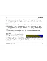
the AOA display. To judge when a stall will occur, remember that the AOA indicator is showing actual AOA, and the 
stall AOA changes with configuration. Because of this, a stall could occur anywhere inside the yellow range, but will 
occur at the same point every time given a specific configuration. Refer to the EFIS-D100 Installation Guide for more 
information on calibrating the AOA indicator. 

Airspeed tape, digital readout, and trend 

The airspeed tape scrolls beneath the airspeed digital readout and arrow. The digital readout’s digits scroll up 
and down, simulating an analog airspeed indicator and giving a sense of the increase or decrease in speed. The 
EFIS-D100 is factory-calibrated to be accurate for airspeeds between 15 and 325 knots (17 to 374 mph). As 
airspeed increases from 0 knots, the indicator becomes active at 20 knots. The indicator remains active until 
airspeed drops below 15 knots. The EFIS-D100 may display airspeeds above 325 knots, but it is not gua
to be accurate. 

ranteed 

The airspeed tape utilizes 4 colors to give you a graphical representation of your speed with relation to your 
aircraft’s limits. By default all of the color thresholds are set at 0, causing a grey tape to be displayed. You 
must set the values of the airspeed color thresholds via the SETUP menu. Refer to the EFIS-D100 Installation 
Guide for more information on setting the airspeed color thresholds. 

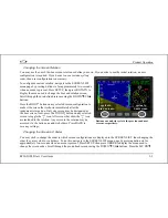
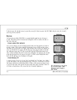
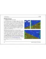
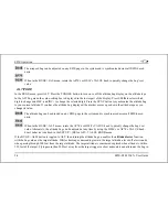
The airspeed trend indicator is located to the left of the airspeed tape. The magenta bar grows in the direction of—and in 
proportion to—the rate of acceleration or deceleration. The trend indicator is scaled to indicate a 6-second airspeed trend. 
In the example at right, the trend indicator is showing that the aircraft will reach 124 knots in 6 seconds if the rate of 
acceleration does not change. 

Bugs 

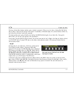
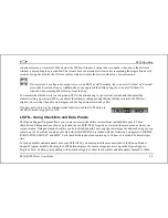
Bugs may be set to mark a desired heading, airspeed, or altitude. These bugs are represented by a yellow 
inverted arrow located at the desired value on the tape. If the set heading, altitude, or airspeed is 
currently off-screen, the bug icon appears at the edge of the moving tape closest to the desired value. 

EFIS-D100 Pilot’s User Guide 

4-7 

Содержание EFIS-D100

Страница 1: ...ctronic Flight I nformation System Pilot s User Guide P N 100477 000 Revision H For use with firmware version 5 4 August 2010 Dynon Avionics This product is not approved for installation in type certificated aircraft ...

Страница 2: ... customers can interact and receive Dynon technical support outside of telephone support hours A key feature of the forum is that it allows the exchange of diagrams photos and other types of files newsletter dynonavionics com Dynon s email newsletter blog dynonavionics com Dynon s blog where you can find new and interesting Dynon related content Copyright 2003 2009 Dynon Avionics Inc All rights re...

Страница 3: ...ICULAR PURPOSE STATUTORY OR OTHERWISE THIS WARRANTY GIVES YOU SPECIFIC LEGAL RIGHTS WHICH MAY VARY FROM STATE TO STATE IN NO EVENT SHALL DYNON AVIONICS BE LIABLE FOR ANY INCIDENTAL SPECIAL INDIRECT OR CONSEQUENTIAL DAMAGES WHETHER RESULTING FROM THE USE MISUSE OR INABILITY TO USE THIS PRODUCT OR FROM DEFECTS IN THE PRODUCT SOME STATES DO NOT ALLOW THE EXCLUSION OF INCIDENTAL OR CONSEQUENTIAL DAMAG...

Страница 4: ...1 Introduction Before You Fly 1 1 OEM Installations 1 1 Warning 1 2 About this Guide 1 2 2 2 1 Product Overview EFIS D100 Hardware 2 1 ADAHRS Operation 2 3 3 3 1 Product Operation Front Panel Layout 3 1 Display 3 2 Menus 3 6 4 4 1 Available Pages EFIS Main pages 4 2 HSI Page 4 9 Times Page 4 10 Lists Pages 4 11 ...

Страница 5: ...formational Items 5 11 DIM Changing screen brightness 5 13 TIMER Setting and using a timer 5 14 OATSET Setting Temperature Offset 5 15 DATLOG Logging and retrieving data 5 15 6 6 1 HSI Operation Required Connections 6 1 Accessing the HSI DG Page 6 1 HSI Display Basics 6 2 Navigation Radio Overlay 6 4 GPS Overlay 6 7 HSI Menu Structure 6 9 7 7 1 Autopilot Operation Introduction and Resources 7 1 EF...

Страница 6: ...isengage Control Wheel Steering CWS Pushbutton 7 15 Optional Preflight Checklist 7 17 8 8 1 Alerts Alarm Indicators 8 1 Multiple Alarms 8 3 DSAB Alerts 8 3 9 9 1 Appendix Appendix A Serial Data Output 9 1 Appendix B PC Support Program 9 3 Appendix C Troubleshooting 9 3 Appendix D EFIS D100 Specifications 9 8 ...

Страница 7: ...nformation that might be needed in flight CAUTION in a flying situation it is the pilot s responsibility to use the product and the guide prudently OEM I nstallations If your EFIS D100 is installed by an OEM distributor you may find that you are unable to access some menus and settings Some Dynon distributors customize various areas of the EFIS D100 firmware to maintain a consistent pilot experien...

Страница 8: ... section references in the Table of Contents and elsewhere act as hyperlinks taking you to the relevant location in the manual The latest version of this manual may be downloaded from our website at docs dynonavionics com This guide discusses the most common operation scenarios If you have an operational issue that is not discussed in this guide you can find additional operational information on D...

Страница 9: ...ystem Any text following this icon describes functionality available only with the AP74 Autopilot Interface Module connected to your system Any text following this icon describes functionality that is possible when multiple Dynon Avionics products are networked together via the Dynon Smart Avionics Bus DSAB Any text following this icon refers to a setting or situation which merits particularly clo...

Страница 10: ...engine start The EFIS D100 can be ordered with an optional internal battery which allows the instrument to continue to operate in the event of an external power failure This lithium ion battery is rechargeable and is managed by the EFIS D100 If the always on Keep Alive circuit is connected the EFIS D100 continues to charge its internal battery even if the instrument is turned off This ensures that...

Страница 11: ...s data can then be viewed on any other screen in the DSAB network For example an EFIS has the ability to display engine monitor information if it is connected to an EMS or FlightDEK D180 Note that the failure of a unit in a DSAB network may cause the loss of some or all data shared between units In the above example if the connected EMS FlightDEK D180 were to fail the EFIS would no longer be able ...

Страница 12: ...HS34 can adjust the barometer or altitude bug The HS34 s HEADING and COURSE knobs affect their respective parameters on the HSI page The HS34 s GPS and NAV buttons cycle through the available GPS and NAV sources connected to it ADAHRS Operation The primary flight instruments on your EFIS display are generated using a group of calibrated sensors All of them are solid state that is there are no movi...

Страница 13: ...ops with your airspeed reading a properly connected and configured GPS source acts as a substitute When in this mode the instrument continues to provide accurate attitude omplex algorithm using a multitude of sensors If a GPS is present upon the loss of airspeed the EFIS D100 uses the GPS ground speed in its attitude calculation When in this mode a magenta GPS ASSIST message is displayed over the ...

Страница 14: ...heck against the EFIS D100 s attitude COMPASS ACCURACY AND AUTOPILOT PERFORMANCE If you are using your EFIS D100 to control Dynon s Autopilot it is critical that the magnetic heading be as accurate as possible for comfortable operation in HDG mode and radio based VOR NAV mode The aircraft s compass must be installed correctly calibrated and operating well in all attitudes ...

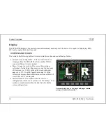
Страница 15: ...uttons There are six buttons on the front panel of the EFIS D100 Throughout this guide these buttons are referred to as one through six with button one being the leftmost and button six being the rightmost EFIS D100 buttons are used to turn the instrument on and off cycle between screens scroll through menus and adjust instrument parameters Display The display shows EFIS information menus and data...

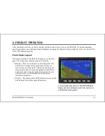
Страница 16: ...oduct Page A page is a section of the screen that contains a collection of related data Pages may occupy the total area of the screen i e 100 or share the screen with other pages e g 2 3 1 3 split Pages that occupy 1 3 of the screen area are sometimes abbreviated versions of their full size 100 or 2 3 counterparts Screen Rotation The rotation is the list of screen configurations which can be cycle...

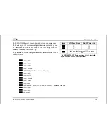
Страница 17: ...rations with their respective icons are as follows EFIS EMS EFIS AUX EFIS FUEL EFIS TIMES EFIS HSI in default screen rotation EMS EFIS EMS AUX EMS TIMES EMS FUEL EMS HSI EFIS default EFIS D100 boot up screen in default rotation EFIS EMS EMS EFIS HSI EMS EFIS D100 Pilot s User Guide 3 3 Icon Left Page Area Right Page Area 2 3 1 3 1 3 2 3 One page that occupies all of the screen area The SCREEN LIST...

Страница 18: ...y either select your currently displayed screen with the caret and press GOTO or press CANCEL Hold two seconds Screen Cycling Using Hotkeys With no menu displayed press button one to cycle to the previous screen in your rotation Likewise press button six to cycle to the next screen in your rotation see the figure on the next page Cycling via hotkeys only allows you to display screens that are in y...

Страница 19: ...on Only one screen may be designated as the boot screen Next press the TOGGL button on any selected screen to toggle the icon All screens that show the icon are included in the rotation Any screen in the rotation may be accessed via the button one and six hotkeys Press BACK to save any settings cycles to prev screen cycles to next screen Buttons one and six cycle to the previous and next screens r...

Страница 20: ...the screen and the right page occupying 1 3 of the screen then pressing EFIS D100 buttons two three or four all below the left 2 3 of the screen displays the main menu for the left page and pressing button five below the right 1 3 of the screen displays the main menu for the right page see the figure to the right FUNCTIONALITY A menu consists of two rows of gray boxes containing text The upper row...

Страница 21: ... positions FLOW Each page has its own main menu which may contain options for navigating to other menus or choosing and adjusting parameters For example the EFIS Main Page menu contains an EFIS menu tab and button labels for MENU BARO BUGS LISTS MORE and EXIT Pressing MORE reveals the rest of the EFIS menu This menu contains options for SETUP INFO DIM TIMER MORE and EXIT Pressing MORE on this menu...

Страница 22: ...e into the menu system DESCRIPTIONS IN THIS GUIDE Throughout this guide the character is used to indicate entering a deeper level of the menu system For example EFIS INFO LEFT indicates entering the EFIS menu pressing MORE then pressing INFO and then pressing LEFT to enter the left info item menu Note that the MORE button is not included in the sequence since pressing MORE reveals more options in ...

Страница 23: ...e data that is obtained from a source external to the EFIS D100 Refer to the EFIS D100 Installation Manual for a list of compatible equipment Note EMS based pages use data that is obtained from Dynon s EMS products You may only display these pages on your EFIS D100 if you own a Dynon EMS based product and the two units are connected via DSAB Refer to the EFIS D100 Installation Manual for details r...

Страница 24: ...creen depending on whether or not they have been enabled in the CLUTTR menu Beginning with firmware revision 3 0 Dynon adopted a dramatically different EFIS display format than it had previously used If your EFIS display does not resemble the layouts shown at right first ensure that you are using firmware version 3 0 or higher Then ensure that the setting at EFIS SETUP STYLE is set to MODERN If yo...

Страница 25: ...TUP CLUTTR ROLL menu has an internal arrow which moves to stay perpendicular to the horizon like a jet EFIS presentation The moving roll indicator type 2 rotates the scale about a stationary internal arrow which points to the current roll angle on the scale like most mechanical attitude instrument presentations Please see the ADAHRS Operation section on page 2 3 for important information about the...

Страница 26: ... gyro North East South and West directions are labeled on the tape N E S and W respectively The digital readout displays your current heading while the surrounding tape scrolls beneath its arrow You may set a yellow bug on this tape as a heading reminder The pointer in the digital readout is hollow to allow the GPS ground track indicator displayed as a magenta arrow to show through A difference be...

Страница 27: ...ude tape scrolls beneath the altitude di and down simulating an analog altimeter and giving a sense of the direction of movement Thousands of feet are displayed using large numbers while hundreds of feet are displayed in smaller numbers The EFIS D100 accurately displays altitudes from 1200 to 30 000 ft 365 to 9144 m The graphical Vertical Speed Indicator is located next to the altitude tape The m ...

Страница 28: ...current airspeed units If the EFIS D100 cannot make an accurate winds aloft calculation the arrow is not displayed and the numbers are replaced by dashes The display of winds aloft requires an active GPS connection and an OAT probe In very light winds the wind speed number is not displayed although the arrow is Angle of attack AOA indicator The angle of attack indicator available only with Dynon s...

Страница 29: ...is not gua to be accurate ranteed The airspeed tape utilizes 4 colors to give you a graphical representation of your speed with relation to your aircraft s limits By default all of the color thresholds are set at 0 causing a grey tape to be displayed You must set the values of the airspeed color thresholds via the SETUP menu Refer to the EFIS D100 Installation Guide for more information on setting...

Страница 30: ...of lateral acceleration If the ball is within the two vertical lines then you are in coordinated flight Altimeter setting display The current altimeter setting is displayed at the bottom right of the screen below the altitude tape The value is shown in either inches of Mercury or millibars depending on your preference set in the EFIS BARO menu Clock timer The clock is displayed in the lower left h...

Страница 31: ...ction as a Horizontal Situation Indicator HSI when it is receiving data from Dynon s HS34 connected to a NAV radio an external GPS or Garmin SL30 Nav radio The HSI information is overlaid on a directional gyro DG representation of the EFIS s stabilized magnetic heading information If no GPS or NAV radio source is present in the system the HSI page will still display the DG but without any addition...

Страница 32: ...MS product The flight timer shows the total amount of time that oil pressure was above 15 PSI since the EMS based product was turned on The trip timer shows cumulative flight time since a manual reset The third line of this section contains the general purpose timer which can be used for a variety of functions including a tank timer The ENGINE TIMERS section is native to the EMS and will not appea...

Страница 33: ...ads dynonavionics com Reference the help file that accompanies this software for more information Menu Pages Available in 1 3 and 2 3 formats Some setup menus require a 1 3 or 2 3 page to display all the available options Menu Pages use a caret symbol to indicate the currently selected line Use the DOWN and UP buttons to scroll through the list of options Any line on a Menu Page that is followed b...

Страница 34: ...table to have the EFIS D100 on during engine crank It immediately powers on upon application of external power BARO Changing Altimeter Setting In the EFIS BARO menu you can adjust the altimeter setting When the BARO menu is displayed the value setting box shows the current altimeter setting The DEC and INC buttons change the altimeter setting by 1 100th inHg or 1 m depending upon your selected uni...

Страница 35: ...ect value minimizing the amount of adjustment needed To turn auto set on or off enter the EFIS SETUP BARO menu and set the ADJUST AT BOOT option to ON or OFF BUGS Setting Bug Markers You can set a marker or bug to display on any or all of the three tapes To do this enter the EFIS BUGS menu or EFIS AP BUGS if an AP is installed and choose the type of bug to configure HDG heading TRK track IAS Indic...

Страница 36: ...e bug to be displayed on the heading tape To sync the bug to your current heading or track press the HEADING knob briefly To toggle the bug on or off push and hold the HEADING knob for more than 1 second When in the BUGS HDG or TRK menu rotate the AP74 s VALUE knob to quickly change the bug s set value Alternately the bug can be adjusted at any time by using the HS34 s or AP74 s VALUE knob Exact i...

Страница 37: ...titude bu to your current alt change its value The altitude bug can be adjusted on any EFIS page in the system and is synchronized across all EFIS based units When in the BUGS ALT menu rotate the AP74 s or HS34 s VALUE knob to quickly change the bug s set n 150 feet of the target Flying more than 200 feet away from the target triggers a short audio alert and alternates the bug in value Alternately...

Страница 38: ...or down When you adjust the altimeter setting enough that the altitu window observe that the audio alert triggers and the bug alternates red and yell If you do not wish to use the altitude alerter fu the BUGS menu to toggle it to OFF LI STS Using Checklists and Data Panels The Dynon Support Program allows you to enter your own checklists or select from included data panels These checklists and dat...

Страница 39: ...t the right 2 3 of the screen displays the checklist while the left side displays a 1 3 format EFIS page See the Dynon Support Program for more detailed information on entering checklists and data panels It can be downloaded from our website at downloads dynonavionics com ...

Страница 40: ...g the EFIS SETUP CLOCK menu displays the local and Zulu times in the value setting box Because local time is usually an offset in hours from Zulu time set the minutes value in the Zulu time portion of the box notice that the local time minutes setting change at the same time Then set the hours for local and Zulu times independently Once you have set Zulu time you should never need to change it as ...

Страница 41: ...EL moves the highlight to the next set of digits The order of selection is 1 Local hours 2 Local minutes adjustable only as hour offsets from Zulu minutes 3 Zulu hours 4 Zulu minutes When connected to a GPS you are not permitted to adjust the Zulu time on the EFIS D100 DEC and INC change the selected set of digits To speed up the process press and hold the desired button If you pass the desired va...

Страница 42: ... the turn rate indicator and associated scale markers AOABAR AOA Bar Toggles the display of the angle of attack indicator The AOA indicator requires the use of a Dynon heated or unheated AOA probe CLOCK Clock Toggles the display of the clock Setting Zulu local and 12 24 hour time is done in the EFIS SETUP CLOCK menu BARO Altimeter Setting Toggles the display of the current altimeter setting also k...

Страница 43: ...mote compass EDC or the FlightDEK D180 does not have an OAT ASTRND Airspeed Trend Toggles the display of the 6 second airspeed trend indicator next to the IAS tape VSI Vertical Speed Indicator 0 Toggles and configures the display of the VSI tape next to the altitude tape The VSI can be hidden N or can be set to 1k 2k or 4k ft min scaling The 200 ft min display is linear throughout the range while ...

Страница 44: ...This can only be displayed when an elevator trim sensor to a DSAB connected EMS device and configured in the CHECK FIRMWARE VERSION The EFIS SETUP VRSION menu gives you two important p firmware version and the number of hours the E ieces of information your EFIS D100 s current FIS D100 has been on If you require technical support or other assi Dynon please have your firmware version ready when you...

Страница 45: ... the amount of acceleration due to the earth s field experienced by an object a level Positive g force is defined as upward vertical acceleration making you feel heavier Negative g force is defined as downward vertical acceleration making you feel lighter As can be seen in the picture there are three rows of text that make up the g meter The top row labeled MX is the maximum positive g force exper...

Страница 46: ...nit tall status on the EFIS D100 has no effect on the displayed OAT Changing screen brightness all units This can be an OAT connected to an EFIS or an EMS in the system changing the OAT type or ins This change is only used if the primary OAT or entire DSAB network fails and the EFIS switches to the locally connected OAT ENGINE Manifold Pressure and RPM The engine informational item allows you to d...

Страница 47: ... se creen he erc rk continue to use the BRITR or DARKR buttons as you would is displayed depending on which timer type 0 00 To reset the timer press the UP DN button twice nsor values are averaged To turn this function on does not immediately change brightness Instead the desired brightness From that point on all networked eived brightness at the desired level If auto dim is without auto dim The s...

Страница 48: ... OAT is connected Ensure that you have indicated that EFIS OAT is not installed enter the EFIS SETUP OAT menu and press INSTALLED until the value is N In the EFIS OATSET menu press INC or DEC until the value setting box above the menu displays the current outside air temperature This value is then used in the OAT TAS DA info item on the EFIS screen For more informatio on setting up that display se...

Страница 49: ...new records overwrite the oldest records To delete the records in internal storage select ERASE LOG ERASE MIN MAX LOG or ERASE SNAPSHOT LOG only available on certain units The data format and connection settings for the internally recorded data are described in the Help Files of the Dynon Support Program downloaded The snapshot log records the value of all parameters anytime an alert occurs To act...

Страница 50: ...ceivers via serial ARINC 429 and analog connection A connection to the HS34 generally carries more information than a serial only connection to an EFIS or EMS when an HS34 is installed connections to navigation receivers and GPSs must be made to it Please see the EFIS D100 Installation Guide for detailed installation and connection information Accessing the HSI DG Page The HSI is displayed as a 1 ...

Страница 51: ...dio VOR LOC is green in color and includes the course course deviation glideslope NAV mode to from OBS setting tuned frequency station identifier and more The final data source is information that comes from the EFIS itself and is color coded in white The EFIS sourced data includes magnetic heading true airspeed winds and various other data points Below are some of the basics 1 Mode flag This indi...

Страница 52: ...ourse to the heading of the back course runway heading of the primary ILS runway causes the CDI needle to be reversed 2 Digital heading indicator The number in this box is the current magnetic heading of the aircraft in degrees from 001 to 360 The accuracy of this data depends on the accuracy of the h 3 Directional Gyro DG The ring of tick marks and numbers acts as a traditional directional gyro T...

Страница 53: ...xt displays located at the top of the HSI Page provide a varie of information Displayed here is the course OBS setting the active frequency that the SL 30 is tuned to the identifier for the tuned frequen active and secondary frequencies When the data is not available or is not valid the various data fields in this area are replaced by dashes 2 Course indicator The green course indicator shown poin...

Страница 54: ...r fu scale represents 2 5 degrees of deviation When on course the course indicator and the CDI ation sent out by make a solid line making it easy to see when there is little error in your aircraft s position Unlike a CDI indicator found in basic aircraft the CDI needle on an HSI rotates with the DG and course indicator By turning the aircraft towards the CDI needle you reduce your deviation 4 To F...

Страница 55: ...ncy A numerical display of your primary labeled NAV and standby labeled SBY bearings and a reminder of which symbol represents each bearing is in the text area of the page The HS34 adds the possibility of having many more bearing sources in the system Pressing the BRG SRC button highlights the first bearing source Turning the VALUE knob allows you to choose your bearing source from all options Pre...

Страница 56: ...e rotation of the DG so it is easy to see which way you must turn to get on course The course indicator is only present when you have an active flight plan in your GPS and are navigating to a point Some GPS units do not report course direction In this case a COURSE menu item is made available in the HSI menu to manually set it PS ion 3 Course Deviation Indicator CDI When a flight plan is active in...

Страница 57: ...ring and a diamond icon to signify its symbol on the display The HS34 adds the possibility of having many more bearing sources in the system so the behavior of the BRG SRC button is dependent on how many devices you have connected When you press this button if you have only one possible bearing source the bearing source toggles on and off If you have two or more bearing sources pressing the BRG SR...

Страница 58: ...ported by the GPS This is different than your magnetic heading when there are crosswinds present Since this is your actual ground track keeping this directly above your course pointer when the CDI is centered keeps you on course even if your magnetic heading is different As long as a valid GPS source is detected by the system the ground track indicator can be displayed This is not dependent on the...

Страница 59: ...tive This is used to set the OBS course The SL 30 does not allow you adjust the OBS when tuned to a localizer so this must be done locally on the instrument When you have an HS34 with any NAV instrument the course knob on the HS34 adjusts the course OBS You can adjust the course when in NAV or localizer mode When using a GPS such as the 430 530 that allows an nt also works If the GPS or NAV urse k...

Страница 60: ...nics AP is that the servomotors servos responsible for actuating the control surfaces are smart devices Dynon s servos not only accept commands from the AP but also report health resistance to commanded movements motor override or slip and many other data elements back to the EFIS This level of communication between AP control and motors provides the pilot with an unprecedented degree of awareness...

Страница 61: ...s an accurate magnetic heading to operate efficiently and comfortably in HDG and NAV VOR modes Therefore it is critical that the aircraft s compass be installed correctly calibrated and operating well in all attitudes EFI S AP I ndicators When 1 or more servos are installed and configured the EFIS D100 s EFIS presentation includes some new indicators described below If these indicators do not appe...

Страница 62: ...isplay of Pitch mode suppressed stalled AP engaged in HDG m AP Status Indicator Modes AP State Roll Display Pitch Display Status Servo disengaged OFF OFF Status Heading Hold Mode AP uses HDG Bug as target magnetic heading HDG N A Status Track Hold Mode AP uses HDG Bug colored magenta as target TRK Magenta Text N A Status Control Wheel Steering Mode When CWS is configured and AP held for more than ...

Страница 63: ...o error condition detected or servo not found Check DSAB configuration wiring and servo power ERR red text ERR red text Any axis that is in any of the above error states cannot be engaged ILURE M FA ODES The EFIS continuously monitors the overall operation of the AP as well as the state of incoming GPS data If an error is detected the subsystem where the error has occurred is restricted and report...

Страница 64: ...e 005 2250FT HDG bug toggled ON set to 005 and ALT bug toggled ON set 2250 Feet In the example at right the heading bug is toggled on i e displayed on the heading tape but the AP HDG mode is currently disengaged BUGS GRAPHICAL APPEARANCE When an AP is installed and configured the appearance of the IAS HDG and AL o is changed to ref respective bug is axis HDG TRK ALT the respective bug is solid or ...

Страница 65: ...s llowing the heading bug colored magenta to signify GPS mode Yo AP controlled aircraft to turn toward the new target ground track In Track Mode the AP s goal in the roll axis is to align the magenta ground track triangle with the inverted triangle of the heading bug 180 180º TURN MODE ROLL AND PITCH SERVOS This special mode is a way to initiate a quick turnaround Whe ltitude and Track Hold modes ...

Страница 66: ...HDG mode if the VOR indicates OFF as when crossing the station NAV LOCALIZER TRACKING MODE ROLL SERVO NAV LOC mode is available whenever a LOC source must be engaged only when the CDI needle is near center not pegged at either end of the scale and the airplane is on a heading near that of the runway Runway heading for the ILS must be set via the OBS NAV LOC mode is indicat e annunciation LOC in th...

Страница 67: ... the aircraft down without going above the ma MAX AIRSPEED REDUCE POWER the ai imum Likewise when the AP is engaged and aircraft airspeed drops below the minimum the AP ente pitching the aircraft down to prevent dropping below the minimum airspeed When target ALT bug and the AP cannot pitch the aircraft up without going below the min the prompt rs an airspeed hold mode rcraft s altitude drops belo...

Страница 68: ...n documentation as EFIS AP This replaces the BUGS menu relocated under the AP menu The AP menu includes the following buttons and functionality BUGS Works as the BUGS menu has in previous firmware versions and is documented on page 5 2 The HDG or TRK note that this bug will display as either HDG or TRK depending on autopilot s mode of operation and ALT bugs now control the targets for the autopilo...

Страница 69: ...g or ground track respectively The heading or track ALTOFF ON The menu label reflects whether the AP is currently engaged in Altitude Mode Pushing this button toggles between ON and OFF activating and deactivating the pitch servo in altitude mode When the Autopilot is engaged in ALT mode the altitude bug is synchronized to the current altitude The altitude bug can then be adjusted while the AP is ...

Страница 70: ...AP button indicator is on the roll servo is active in Heading Mode If the AP button i is off the roll servo is armed in Heading Mode ndicator TRK button indicator ON when lateral roll servo is armed or active in Track Mode NAV button indicator ON when lateral roll servo is armed or active in Navigation Mode ALT button indicator ON when vertical pitch servo is armed or active in Altitude Mode AP74 ...

Страница 71: ...tem completely Pushing and holding the knob while changing a bug synchronizes the bug to the current value Pushing and holding the knob while changing the BARO sets the barometer to 29 92 inHg Further behavior can be configured as described on page 7 13 HDG Button When its indicator is off pressing the HDG button arms the roll servo in Heading Mode and turns on the indicator Depending on how you h...

Страница 72: ...T button Read Pre select Configuration on page 7 14 for more details on configuring this behavior for your needs The altitude bug can then be adjusted while the AP is engaged When its indicator is on pressing the button disarms deactivates the pitch servo and turns off the button s indicator When ALT mode is deactivated the altitude bug is toggled off disabling the altitude alerter VALUE KNOB CONF...

Страница 73: ...hrough the remaining modes not chosen by FIRST ACTION above Pushing the VALUE knob cycles through these modes in the order BARO ALT HDG off If there is no further action either a knob push or knob rotation within 5 seconds the pop up window automatically closes PRE SELECT CONFIGURATION In the BUGS section of the AP74 76 SETTINGS menu you can choose when the heading and altitude bugs should be sync...

Страница 74: ...w modes prior to re engaging the AP If you select YES the AP disarms all modes upon disengaging the AP turning off all mode lights on the AP74 You must then select the active modes prior to re engaging the AP although if no modes are pre armed pressing the AP button causes the HDG mode to be engaged by default Clearing modes on disengage is most useful when used in conjunction with the ON MODE ARM...

Страница 75: ...ondary mode of the AP Disengage CWS Button This mode allows you to be flying under AP control press and hold the Disengage CWS Button while flying to a new heading and or altitude then release the button to reengage the Autopilot The Autopilot reengages in the mode set by the MODE parameter described below Note that while holding down the button the AP status indicator at lower left of the EFIS sc...

Страница 76: ...the servos powered OFF test the controls for proper operation of the control surfaces The controls should feel normal the servos should add little resistance The EFIS D100 should display an alert regarding DSAB connectivity Additionally the AP Status display should show AP ERR ERR 2 With circuit breaker for the servos powered ON observe the EFIS Verify that the AP Status indicator now shows AP OFF...

Страница 77: ...n the EFIS D100 is for AOA and autopilot alerts only If you have a Dynon EMS based product installed connected to both your EFIS D100 and cockpit audio system EMS based alarms will still sound an audible alarm If your EFIS D100 is networked to other Dynon products via DSAB alarms sourced from those products will appear on your EFIS D100 as well Alert messages sourced from your EFIS D100 are preced...

Страница 78: ...m indications and return to your original screen ALARM ACKNOWLEDGEMENT To acknowledge the alarm press the ACK button The ACK button has a number next to it indicating the number of currently posted alarms If this number is higher than 1 after you press ACK you will see the alarm text for the next posted alarm Pressing ACK does the following Removes the alarm bar and alarm menu if no other alarms a...

Страница 79: ...own DSAB Alerts When multiple Dynon Avionics instruments are networked together via DSAB there are a few error messages designed to warn you of failures or reduced functionality NETWORK CONFIGURATION ERROR This error can only occur within a short period of time after the system is turned on This error indicates that a unit that was expected to be on the DSAB network was not found For example if in...

Страница 80: ...subsystem failures such as an EDC or an OAT In these cases the device falls back to a local OAT or EDC if it is available The INSTRUMENT FUNCTION LOST message is preceded by THIS or DSAB on each connected display instrument If the label is THIS then the screen with this label is the source of the failure If the message begins with DSAB than the message indicates a failure on another device This me...

Страница 81: ...formation on the installation and connection to these serial ports can be found in the EFIS D100 Installation Guide To log EFIS data you must connect the serial port to a PC This serial data can be logged using any standard serial terminal program such as HyperTerminal It can then be parsed into its respective columns by many spreadsheet programs including Microsoft Excel All numbers are output in...

Страница 82: ... in 1 10 degrees 1800 180o 18 3 Yaw 000 to 359 in degrees 000 North 090 East 180 South 270 West 21 4 Airspeed 0000 to 9999 airspeed in units of 1 10 m s 1555 155 5 m s 25 1 Altitude Sign or positive means altitude is above sea level 26 4 Altitude 0000 to 9999 altitude in units of meters alternates between pressure and displayed altitude depending on status bitmask starting at character 42 30 1 Tur...

Страница 83: ...de and VSI is output in characters 30 33 48 2 Internal use Internal use ignore 50 2 Checksum The ascii hex 2 byte sum of all 49 preceding bytes 52 2 CR LF Carriage Return Linefeed 0x0D 0x0A As an example the following is what one line of serial data looks like 00082119 058 00541301200 9141 011 01 15003EA0C701A4 CR LF Appendix B PC Support Program Dynon offers a free PC Support Program which allows...

Страница 84: ...isplayed by the EFIS D100 The list provides information about what they mean and what to do about them DISPLAYED ALERT MESSAGES The following table describes the alert messages that the EFIS D100 can display Alert Message Description End condition INTERNAL ERROR SERVICE UNIT This error can occur for a few reasons including an aborted upload It signifies that the EFIS D100 has detected internal pro...

Страница 85: ... flight TEMPERATURE UNSTABLE When the unit is turned on after having been off for a long period its internal temperature will rise above ambient at a fast rate This fast change in temperature can sometimes reduce the reliability of the output of the sensors Therefore this alert is displayed and the horizon indication is changed from blue brown to grey black The screen remains normal color but the ...

Страница 86: ...r the external backup battery or Master Power At that point the battery will begin charging off the external power REMOTE COMPASS NOT DETECTED The EFIS D100 is unable to communicate with the EDC D10A If you have an OAT connected to your EDC D10A you will lose this reading as well Ensure that you a have an EDC D10A installed and b have verified that the wiring to the EDC D10A is correct Please see ...

Страница 87: ...his alert appears when the EFIS has an OAT connected and then loses that connection for some reason Either the EDC D10A has become disconnected or the OAT sensor itself has become disconnected from the EDC D10A Double check your wiring between the EFIS D100 and the EDC D10A as well as that of the OAT sensor ...

Страница 88: ...t 2 lb 13 5 oz 1 29 kg 3 lb 4 oz 1 47 kg with internal battery AP74 10 7 oz HS34 11 3 oz Operating Temperature 22 to 122 F 30 to 50 C Power Voltage 10 30 Vdc Power 12 watts typical 17 watts maximum Connections Wiring D 25 male Screen Type AMLCD TFT Thin Film Transistor Backlight 400 nits or 800 nits Size 7 0 diagonal 178 mm Resolution 854 x 480 color pixels ...

Страница 89: ...Appendix EFIS D100 Pilot s User Guide 9 9 Inputs Outputs 1 Audio Alarm 1 RS 232 bidirectional PC communication 1 RS 232 data input GPS SL30 etc 1 Dynon Smart Avionics Bus DSAB ...

Отзывы: