HSI Operation
GPS Overlay
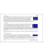
The figure at right shows an HSI page with information sourced from a GPS receiver while the
GPS has an active flight plan between two points. The various elements are described below.
1.
Text displays. In this area a variety of information is displayed in text format.
Displayed here is the ground track (TRK), the course (CRS), ground speed (SPD),
distance to next waypoint (DTW), and up to two bearing pointer selections.
2.
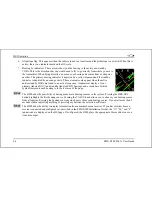
Course indicator. The course indicator points in the direction of the course that the G
is reporting*. This is usually the direction of the line between the start and end
waypoints. This setting is also shown in the text area as "CRS." In a situation with no
winds, keeping the course indicator pointed straight up and in line with the heading
pointer keeps the aircraft on course. This indicator is fixed to the rotation of the DG, so
it is easy to see which way you must turn to get on course. The course indicator is only
present when you have an active flight plan in your GPS and are navigating to a point.
*Some GPS units do not report course direction. In this case, a COURSE menu item is made
available in the HSI menu to manually set it.
PS
ion.
3.
Course Deviation Indicator (CDI). When a flight plan is active in the GPS, the CDI indicates
how far to the left or right of your selected ground course you are (CDI in large oval at right).
Depending on the scale that you are in, each dot indicates 0.06 n.m. (Approach), 0.2 n.m.
(Terminal), or 1.0 n.m. (Enroute). When on course, the course indicator and the CDI make a
solid line, making it easy to see when there is little error in your aircraft's position. Unlike a
CDI indicator found in basic aircraft, the CDI needle on an HSI rotates with the DG and
course indicator. By turning the aircraft towards the CDI needle so the CDI needle is "on top"
of the course line you reduce your deviat
EFIS-D100 Pilot’s User Guide
6-7


