background image

8

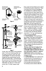
Support, refer to the Square ceiling installation 

below.  The Round Ceiling Support Box has 

the option of a square or round Trim Collar 

available 

(Fig 5)

.  The bottom of the Round 

Support Box must extend at least 3 inches 

below the finished ceiling.  Level the Support 

Box and secure it to the framing using at least 

three 8-penny nails per side (min. of 12 total).  

Alternatively, you may use 1-1/2” #8 wood 

screws (min. of 12 total), instead of nails.  

Next, secure the Trim Collar (round or square) 

to the framing members using the (4) 1” long, 

round-head wood screws provided 

(Fig 6)

For installation into a cathedral ceiling, you 

must use the Square Ceiling Support Box or 

Reduced Clearance Support Box (or the CAS 

Ceiling Support if installing the CAS system) 

and the two-piece Trim.  The bottom of the 

square portion of the Support Box must be a 

minimum of 2-inches lower (round portion is 

an additional 3 inches lower) than the finished 

ceiling at the lowest side of the penetration 

(Fig 5 & 6)

.  Level the Support Box and 

secure it to the framing using at least three (3) 

8-penny nails per side (minimum of 12 nails 

total), or a minimum of (3) #8, 1-1/2” wood 

screws.  Adjust the overlapping “U-shaped” 

Trim pieces so they cover the Support Box, 

and secure them to the framing members 

using the (6) 1-1/4” long, round head wood 

screws provided 

(see Fig 6)

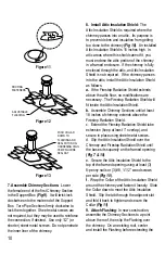
4.  Frame Openings:

  Frame openings in 

each ceiling or floor above the Support Box 

(Fig 7)

.  These openings are to hold the 

Firestop Radiation Shield and Attic Insulation 

Shield.  Locate each opening by dropping a 

plumb bob to the four corners of the opening 

below.  Maintain the framing dimensions as 

specified in 

Table 2

.  


Warning: other than the framing for the 

Reduced Clearance Support Box, any 

combustible materials around the chimney 

must still meet the minimum 2” clearance 

requirement. 

If Elbows must be used to 

avoid an obstruction, refer to the Offset Elbow 

Installation section.  

5.  Cut Roof Opening:

 Cut an opening in the 

roof directly above the opening below, and 

at least 4 inches larger than the chimney’s 

outside diameter to provide at least a 

2-inch clearance all around the chimney.  

The chimney must be centered within this 

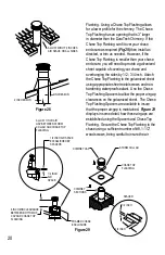
Figure 6

Figure 7

MIN OF 2 

INCHES 

BELOW 

FINISHED 

CEILING

WOOD SCREWS ARE 

REQUIRED

WOOD SCREWS ARE 

REQUIRED

ROUND CEILING 

SUPPORT WITH TRIM 

IN PLACE

SQUARE CEILING 

SUPPORT BOX WITH 

TRIM FRAME 

IN PLACE

CAP

ADJUSTABLE 

FLASHING

CHIMNEY 

SECTION

ATTIC 

INSULATION 

SHIELD

STORM 

COLLAR

FIRESTOP 

RADIATION 

SHIELD

CHIMNEY 

SECTION

FRAMED 

ENCLOSURE

2 INCH MIN 

CLEARANCE 

TO INSIDE OF 

ENCLOSURE

MIN OF 3 

INCHES BELOW 

FINISHEDCEILING

18 INCH MIN FOR 

SINGLE WALL 

STOVEPIPE

Содержание DuraTech Series

Страница 1: ...DuraTech All Fuel Chimney System 5 to 8 diameter Installation Instructions...

Страница 2: ...ep these instructions for future reference This booklet also contains instructions for installing a venting system within an existing masonry chimney and for installations passing through a cathedral...

Страница 3: ...EP DIRECTIONS 6 CEILING SUPPORTED 7 OFFSET ELBOW INSTALLATION 11 EXTENDED ROOF BRACKET INSTALLATION 13 ROOF SUPPORTED INSTALLATIONS 13 TEE SUPPORTED INSTALLATIONS 16 MASONRY FIREPLACE INSTALLATIONS 21...

Страница 4: ...actory built fireplaces check with your fireplace manufacturer Otherwise DuraTech has not been approved for use with solid fuel appliances in Canada DuraTech Chimney is available in 5 6 7 8 diameters...

Страница 5: ...Shield Elbow with swivel Attic Insulation Shield Tee with Tee Cap Elbow Strap Adjustable Tee Support Bracket Adjustable Wall Strap Chimney Cap Anchor Plate Round Ceiling Support Box Extended Roof Bra...

Страница 6: ...mation and enhance draft Include an access door by the Tee Cap for chimney cleaning Refer to Fig 23 STOVE RECOMMENDATIONS Follow the stove manufacturer s instructions The requirements stated below per...

Страница 7: ...d Support Box the Flat Ceiling Support Box the Square Ceiling Support Box Reduced Clearance Support Box or the CAS Ceiling Support The CAS Ceiling Support is only used when installing the CAS system R...

Страница 8: ...pport Box and secure them to the framing members using the 6 1 1 4 long round head wood screws provided see Fig 6 4 Frame Openings Frame openings in each ceiling or floor above the Support Box Fig 7 T...

Страница 9: ...is on the ground floor Support Box is in the 1st floor ceiling you would need a Firestop Radiation Shield at the 2nd floor ceiling and at the 3rd floor ceiling etc including where the chimney penetra...

Страница 10: ...ion Shield until the base sits squarely on the framed opening Fig 7 10 e Secure the Attic Insulation Shield to the top of the framed opening using at least 3 8 penny nails or 3 8 1 1 2 wood screws per...

Страница 11: ...the cap and twist locking it clockwise onto the chimney Do not hold upper portion of the cap and twist as this may damage the cap The Chimney Cap can be removed for chimney cleaning as described in t...

Страница 12: ...8 38 15 36 11 50 15 48 14 61 15 48 6 15 66 15 48 12 17 72 15 48 18 18 78 15 48 24 20 83 30 0 4 15 30 6 6 30 12 9 25 30 18 12 30 30 24 15 35 30 36 21 46 30 48 27 56 30 48 6 29 60 30 48 12 32 65 30 48 1...

Страница 13: ...bottom halves of the Adjustable Leg In order to secure Legs in proper position there is a hole provided in the outer leg where the outer and inner halves overlap Use a 1 4 drill bit to drill through...

Страница 14: ...install the remainder of the Combustible Air System The Support Box must remain level and the top edge of the box must cover the edge of the roof s decking material Square Ceiling Support Boxes are a...

Страница 15: ...im sections into the ceiling Fig 6 4 Complete Installation Refer to Steps 7 9 10 in the Ceiling Supported Installation section to complete the Roof Supported installation Figure 20 Figure 21 2 A Roof...

Страница 16: ...ers Please note that you cannot extend the chimney all the way to the appliance you must have some connector pipe 1 Cut and frame opening to provide a minimum of 2 clearance on all sides of the chimne...

Страница 17: ...uter walls at this location Refer to Table 2 for the appropriate framing dimensions 3 Install Wall Thimble The Wall Thimble is two piece component which includes the Interior half and the Exterior hal...

Страница 18: ...ust for desired clearance to wall and secure by tightening bolts Figs 26 27 5 Install Tee and Cleanout Chimney Figure 25 Figure 26 INSTALLATION WITH TEE BELOW TEE SUPPORT SHOWN WITH LEG BRACKETS MOUNT...

Страница 19: ...on to the female end of the Chimney Branch by twisting clockwise 8 Complete Chimney Attach the Chimney Sections as in Step 7 in the Ceiling Supported Installation section Secure the chimney to the wa...

Страница 20: ...e the Chase Top Flashing Spacers to allow the proper air gap clearances on the galvanized sheet The Chase Top Flashing Spacers are available to insure that the proper air gap is maintained Figure 29 d...

Страница 21: ...th a high temperature 1000 F sealant Secure Anchor Plate with at least 4 1 4 x 4 masonry anchors Fig 30 It is very important that the Anchor Plate is level Be sure to maintain a 1 min clearance to com...

Страница 22: ...he Slip Connector or Snap LockAdapter slips into the opening in the Ceiling Support or Finishing Collar Align the tabs on the Slip Connector or Snap LockAdapter with the notches in the face of the Sup...

Страница 23: ...sk of chimney fire 4 How to Clean Have your chimney cleaned by a Certified Chimney Sweep if you have doubts about your ability to clean it Use a plastic wood or steel brush Do not use a brush that wil...

Страница 24: ...Sweep orVENTINOX installer The Liner and Components warranty is further subject to compliance with the following requirements throughout the warranty period The chimney must have a chimney cap and che...

Отзывы: