81
1 1 5 0 / 1 1 5 5 H A Y B U S T E R T U B G R I N D E R O P E R A T I N G I N S T R U C T I O N S
ELECTROHYDRAULIC VALVE COIL TEST (FOR S.N. 0167 AND UP)
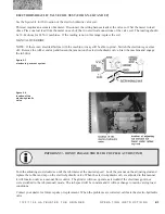
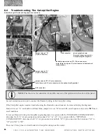
See the figure 6.4 for the location of the electro‑hydraulic valve coil.
This test requires an accurate ohm meter. Disconnect the wiring harness leads at the valve coil. Set the meter to read
ohms. Place one test lead from the meter on each of the two electrical connections of the valve coil. The reading should
be 39-44 ohms for 24 Volt machines. If the reading is not in this range, replace the coil.
MANUAL OVERRIDE
NOTE: If there is an electrical failure with the machine, it may still be able to grind. Switch the electronic governor
off. Remove the rubber end cap and loosen the jam nut on the electro-hydraulic valve. Start the machine and engage
the tub drive.
figure 6.3
electronic governor system
IMPORTANT! - DO NOT ENGAGE THE FLUID COUPLER AT THIS TIME!
Turn the adjusting stud clockwise until the tub rotates at the desired speed. Lock the jam nut on the adjusting stud and
replace the rubber end cap on the electro-hydraulic valve. When the electro-hydraulic valve is adjusted in this manner,
it will function only as a manual flow control. The grinder will now operate as it would if the electronic governor
were switched to the tub (manual) mode. The tub speed will be constant and it will not change to match varying load
conditions.
Contact your dealer for future repairs or replacement. When the problems are corrected, calibrate the electro-hydraulic
valve.
figure 6.4
location of the
electro-hydraulic
valve
Содержание Haybuster 1150
Страница 2: ...A Tradition of Innovation Since 1966 ...
Страница 4: ...A Tradition of Innovation Since 1966 ...


