background image

12

Preparation Before Use

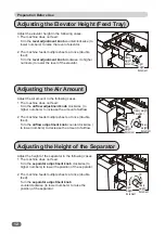
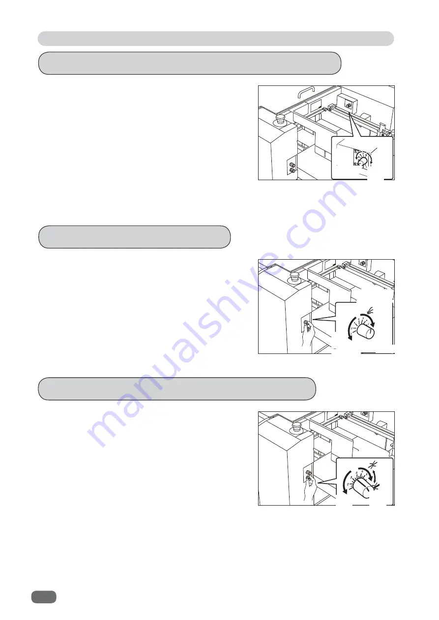
 Adjusting the Elevator Height (Feed Tray)

 Adjusting the Height of the Separator

 Adjusting the Air Amount

Adjust the elevator height in the following cases.
1. The machine does not feed:

Turn the 

level adjustment knob

 counterclockwise (to 

lower numbers) to raise the level of elevator.

2. The machine feeds multiple sheets at once (double 

feed):
Turn the 

level adjustment knob

 clockwise (to higher 

numbers) to lower the level of the elevator.

Adjust the air amount in the following cases.
1. The machine does not feed:

Turn the 

air

fl

 ow adjustment knob

 clockwise ( to 

higher numbers) to increase the amount of air

fl

 ow.

2. The machine feeds multiple sheets at once (double 

feed):
Turn the 

air

fl

 ow adjustment knob

 counterclockwise ( 

to lower numbers) to decrease the amount of air

fl

 ow.

Adjust the height of the separator in the following cases:
1. The machine does not feed:

Turn the 

separator adjustment knob

 clockwise (to 

higher numbers) to lower the position of the separator.

2. The machine feeds multiple sheets at once (double 

feed):
Turn the 

separator adjustment knob


counterclockwise (to lower numbers) to raise the 
position of the separator.

Heavy weight 

document

document

Heavy 

weight 

document

Heavy 

weight 

document

Heavy 

weight 

document

Light 

weight 

document

Light 

weight 

document

Light 

weight 

Содержание DC-516

Страница 1: ......

Страница 2: ......

Страница 3: ...nterests of upgrading our product specifications and other data given in this manual are subject to change without notice If the manual contains anything that you do not understand contact the dealer...

Страница 4: ...ctos cumple con las disposiciones previstas en los reglamentos Seguidamente se indica la tabla de referencia Depositario del archivo t cnico en la Comunidad Europea Duplo International Ltd Sandown Ind...

Страница 5: ...produit ne doit pas tre limin comme des ordures m nag res Recyclez le dans les sites adapt s qui vous seront indiqu s par les autorit s locales ou renseignez vous aupr s de votre fournisseur En veill...

Страница 6: ...es of Pictorial Symbols WARNING CAUTION Precautions for Use Safety Precautions If the machine is used after foreign matter metal fragments water or liquid has entered the machine this may result in fi...

Страница 7: ...ck Do not remove or insert the power plug with wet hands Doing so may result in electric shock Do not damage break or modify the power cord Do not place heavy objects on tug or bend it unnecessarily D...

Страница 8: ...les Leave the power cord unplugged when the machine is not used for a long period The insulation may deteriorate and cause electrical fire WARNING Do not expose your eyes to the laser radiation either...

Страница 9: ...rforation unit option contain uncovered upper and lower tools Keep your hands or fingers off inside those Use tweezers or a similar tool to remove a jammed document Be sure to unplug the power cord be...

Страница 10: ...ty Labels Keep the safety labels clean at all times If the labels become damaged or come off contact our service person No Part No Name Q ty 1 M7 T303 ENGLISH WARNING LABEL 2 M7 T307 OTHER WARNING LAB...

Страница 11: ...Read and Observe No Part No Name Q ty 2 U7 109 LABEL 1 No Part No Name Q ty 3 U7 T108 LABEL 1 The symbol in the LABEL indicates the elevator down switch The symbol in the LABEL indicates the power sw...

Страница 12: ...rve Label of High Voltage Warning There is a high voltage area inside the machine No Part No Name Q ty 1 U7 T102 CAUTION LABEL 1 230 V model only The safety symbol in the WARNING LABEL indicates risk...

Страница 13: ...bserve Location of Rating Labels Rating labels are located as shown below 1 2 Weight 131Kg Short circuit rating 24A ac Electrical diagram Y2 V700 Date of mfg Address of the manufacturer 353 Koudai Kin...

Страница 14: ...of an operator When you need to stop the machine for emergency press the emergency stop switch Turning the switch to the right releases the emergency stop To stop the machine normally press the STOP k...

Страница 15: ...y interlock system functions when the cover is opened and the machine stops running It is the function for keeping you safe and for avoiding any danger operations or situations by the limitation of op...

Страница 16: ...xiv Notes on Safety Please Read and Observe Machine Dimensions and Required Space for Operation 2125 1510 1375 795 Unit mm...

Страница 17: ...ON 9 Turning Power OFF 9 Preparation Before Use 10 Loading Documents 10 Adjusting the Elevator Height Feed Tray 12 Adjusting the Air Amount 12 Adjusting the Height of the Separator 12 Skew Adjustment...

Страница 18: ...Retrieving a Saved JOB by JOB Number 70 Retrieving a Saved JOB by JOB Log 75 Retrieving a Saved JOB by Category 76 Processing a JOB in Pause Feeding Mode 78 Process 79 Adjust 83 System 86 Environment...

Страница 19: ...re Use 10 Loading Documents 10 Adjusting the Elevator Height Feed Tray 12 Adjusting the Air Amount 12 Adjusting the Height of the Separator 12 Skew Adjustment 13 Adjusting the Suction Skew 14 Setting...

Страница 20: ...the separator and the conveyance belt when a document is not fed or is double fed 6 Airflow adjustment knob Adjusts airflow level when a document is not fed or is double fed 7 Skew adjustment knob Ad...

Страница 21: ...Receives finished products 2 Side guide Set this according to the document size 3 Back guide Prevents finished products from dropping off 4 Waste box Receives pieces of waste paper 5 Power switch Pre...

Страница 22: ...em in the creaser module 4 Creaser tool concave tool convex tool You can pull the creaser tools out with the creaser module installed in the machine and change directions up down of the tools 5 Suctio...

Страница 23: ...er tool concave tool You can pull the creaser tool out with the creaser module installed in the machine and change directions up down of the tool Do not run the DC 516 without creaser tools convex and...

Страница 24: ...6 Part Names and Their Functions Cutter Module No Name Function 1 Cutter module A cutter tool is attached to this 1...

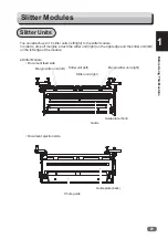
Страница 25: ...is Machine 1 Slitter Module No Name Function 1 Gauge Use this when deciding a position of the slitter unit 2 Slitter unit right Slits a document in the document feed direction 3 Slitter unit left Slit...

Страница 26: ...return the current screen to the main screen or to stop processing 4 TEST key One sheet document is processed to test the current JOB details Press this to check if the document is processed properly...

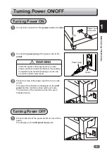
Страница 27: ...Power ON OFF Connect the connector of the power cord to the inlet Connect the power plug of the power cord to the outlet Insert the power cord plug securely so that proper electrical contact is effec...

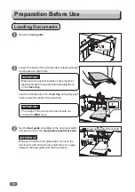
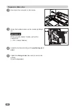
Страница 28: ...ne Make sure to loosen the stack of documents by flipping through the sheets before loading them on the feed tray Raise the back guide Set the feed guide according to the document width and secure it...

Страница 29: ...documents In this case use the guide Set the side guide according to the document size If double feed occurs when using light weight documents adjust the document holder according to the documents RE...

Страница 30: ...adjustment knob clockwise to higher numbers to increase the amount of airflow 2 The machine feeds multiple sheets at once double feed Turn the airflow adjustment knob counterclockwise to lower number...

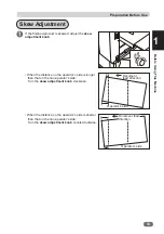
Страница 31: ...on operator s side Turn the skew adjustment knob clockwise When the distance on the operator s side is shorter than that on the non operator s side Turn the skew adjustment knob counterclockwise If th...

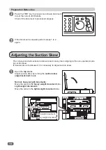
Страница 32: ...djustment knob inside Adjusting the Suction Skew The conveyance belt suctions documents and convey them aligning to the non operator s side by suction skew If documents are fed skewed it is necessary...

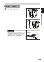
Страница 33: ...row in the figure on the right to open the exit tray There are four setting positions of the exit tray When the finished products size is A3 11 17 or longer or a document adheres to the exit tray due...

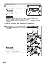
Страница 34: ...cker Option Attach the card stacker when making card sized products Remove the side guides and the back guide attached to the exit tray Set the exit tray upward as shown in the figure on the right Pla...

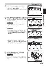
Страница 35: ...is viewed from the front When the alignment of the finished products is poor shifting each guide to the position where it touches the finished products may improve the alignment When there is a gutter...

Страница 36: ...ocessing of all the documents on the feed tray When the number of a preset is programmed it processes as many sheets as the number of the preset Insert the support guide in this gap Support guide Supp...

Страница 37: ...p cover Loosen the two fixing screws on the module in slot 1 Grasp the handles to take out the module by lifting it up Open the top cover Loosen the two fixing screws on the module in slot 2 Install t...

Страница 38: ...e Grasp the handles to take out the module by lifting it up Install the module according to the positioning pin of slot 2 Tighten the fixing screws two each to secure the module Close the top cover Wh...

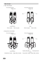
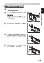
Страница 39: ...In order to drop off margins attach the slitter unit right on the right edge and the slitter unit left on the left edge of the module Slitter Module Document feed side Document ejection side Guide pla...

Страница 40: ...right Slitter units left right Document feed side Document ejection side Margin slitter units left right Document feed side Document ejection side Margin guide left Margin guide right Knob Thumb scre...

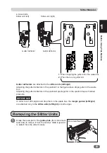
Страница 41: ...ition 1 in the figure above drops gutter in the waste box Adjusting the gutter deflectors in the position 2 ejects gutter in the ejection tray as finished products In order to cut off margins and drop...

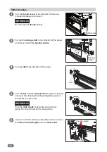
Страница 42: ...t while pulling them gently in the direction of the arrow Hold the slide shafts horizontally and pull them gently Do not pull them with a strong force Loosen the thumb screws on the slitter units to r...

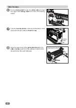
Страница 43: ...hafts before the installation Failure to do so could lead to mechanical malfunction or disorder Insert the edge of the slide shafts in the circled part Turn the dial in the direction of the arrow unti...

Страница 44: ...lower left and the lower right parts Put the driving shaft though the slitter units and insert the edge of the driving shaft in the hole of the bearing holder Inset the bearing holder in the hole of...

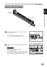
Страница 45: ...o be made When adjusting margins set the scale to margin dimension 50 mm Divisions can be adjusted by 0 05 mm One division is 0 05 mm Read the division of the vernier when the vernier and the main sca...

Страница 46: ...ew of the slitter unit right and move it in the direction of the arrow so that the pin of the slitter unit is located within the gauge Have the pin of the slitter unit come into contact with the U sha...

Страница 47: ...If you cannot adjust the position of the slitter unit left because the gauge comes into contact with it set the gauge in the opposite orientation In order to adjust the next slitter unit position hav...

Страница 48: ...module to remove it from the catcher Slide it upward to detach from the slitter module Insert the collar part of the guide in the edge of the elongate hole of the guide plate front Slide the guide to...

Страница 49: ...Make sure to insert it so that the proper groove faces upward The creaser convex tool is used both for light weight documents and for heavy weight documents Document feed side REFERENCE REFERENCE Cre...

Страница 50: ...ave tool one by one Make sure to pull out both of them Switch the creaser convex tool and the creaser concave tool and insert the tool in the position in the figure Insert the tool securely until it s...

Страница 51: ...y weight documents Make sure to insert it so that the proper groove faces upward Hold the knob and close the insert cover REFERENCE IMPORTANT Do not run the DC 516 without creaser tools convex and con...

Страница 52: ...in laser sensor and adjusts the cut slit crease position accordingly When using REG mark enter the REG mark position in a JOB and set REG Mark to ON To use this function each document must have REG ma...

Страница 53: ...rk should enter into the gray colored area REG mark When there are scratches or stains in the printing range of the REG mark the position may not be corrected When the read side of the document is rou...

Страница 54: ...ument lead edge and the first end mark between the end marks 2 mm or more 1 mm or more after the second end mark No other printings than end mark should enter into the gray colored areas of front and...

Страница 55: ...ogram a JOB make function settings and adjust each function Before Programming a JOB 38 Standby Screen 38 Enter JOB Screen 43 Programming a JOB 50 Programming a JOB with Template 50 Programming a JOB...

Страница 56: ...ch separation Stacker adjustment mode 6 Mark reading Displayed when REG Mark REG mark reading and or End Mark are set 7 Adjust all Displayed when Adjust All is set 8 Apply shrinkage Displayed when App...

Страница 57: ...OB Detail screen of the JOB selected You can check the details of the settings Touching the return icon returns to the standby screen Touching the REG mark adjustment mode icon 14 displays the REG Tes...

Страница 58: ...appears The figure on the right shows REG READ ERROR 2 screen 2 Position adjustment Open the top cover and the take out the module set in slot 1 Close the top cover Load a document with REG mark print...

Страница 59: ...t strikes the central point of the horizontal line of the REG mark The vertical line is not included 1 Measure the distance between the left edge of the document and the point that the laser sensor st...

Страница 60: ...return icon returns to the standby screen Touching the shortcut icon jumps to the item set in Environment and displays the relevant items To make settings for the shortcut icon refer to step 9 in Sho...

Страница 61: ...tly JOBs of the 50th to 55th ahead are displayed JOBs of the 5th to 10th ahead are displayed JOBs of the 5th to 10th behind are displayed JOBs of the 50th to 55th behind are displayed Detail Copy JOB...

Страница 62: ...ears without locking the JOB selected The JOB number of the JOB overwritten is highlighted To unlock the JOB 1 Select a JOB to be unlocked on the Enter JOB screen and touch the JOB lock icon 2 The scr...

Страница 63: ...screen of the JOB selected 2 To save the copied JOB to overwrite an already saved JOB selected touch Overwrite To save the copied JOB as a new one touch Save as Different JOB No After the JOB is saved...

Страница 64: ...w down icon displays the following items in the next page 3 Slot1 The details of settings of the module in slot 1 are displayed Module name Tool direction displayed when the creaser module is used Pro...

Страница 65: ...HWWLQJV 6ORW 0RGXOH 5 Module The module name and tool type in slot 1 are displayed Touching the arrow down icon displays the details of the settings for slot 2 The module name and tool type in slot 2...

Страница 66: ...document and each cut position The DC 516 can cut up to 30 positions on one document Crease position Enter the distance between the lead edge of a document and each crease position The DC 516 can crea...

Страница 67: ...Before Programming a JOB 49 Programming JOB 2 Cutter speed This sets cutting speed Crease depth 1 2 This sets the depth of a crease when creasing a document Speed This sets processing speed...

Страница 68: ...is displayed on the touch panel Touch Enter JOB Programming a JOB with Template JOBs of the 50th to 55th ahead are displayed JOBs of the 5th to 10th ahead are displayed JOBs of the 5th to 10th behind...

Страница 69: ...acter This moves the cursor leftward arrow left icon This moves the cursor rightward arrow right icon When you have finished entering the JOB name touch SET Touching the space icon makes space between...

Страница 70: ...ument of 55 0 91 0 is programmed as cards of 3 in widthwise and 2 in lengthwise 2 XW 6OLW 6 7 RQH The module setting screen is displayed Select and touch either module icon on the lower part of the sc...

Страница 71: ...1RW HQRXJK VOLWWHUV 5HYLHZ WKH FDUG URZV RU JXWWHU VOLWV 1RW HQRXJK 6OLWWHU 5 DQQRW SURFHVV PDUJLQ 5 1 7 1RW HQRXJK 6OLWWHU DQQRW SURFHVV PDUJLQ 1 7 Slitter error messages 1 When there are not enough...

Страница 72: ...r tools are installed in such a way that they cannot drop off the left margin 8 When the slitter tools are installed in such a way that they cannot drop off the right margin 1R VOLW ZLWKLQ PP IURP WKH...

Страница 73: ...H VOLW SRVLWLRQ SURJUDP 9 When the width of the finished product exceeds the specifications Cutter error messages 1 When the total cut is 31 or more out of specifications 7RWDO FXW H FHHGV WKH VSHF 5H...

Страница 74: ...een the lead edge of the finished product and the second crease 5 Distance between the lead edge of the finished product and the third crease 6 Distance between the lead edge of the finished product a...

Страница 75: ...rter than 42 mm are chopped up and dropped into the waste box Trail margin shorter than 67 mm are chopped up and dropped into the waste box Settings 1 Air Knife If document double feed occurs frequent...

Страница 76: ...are ejected to the exit tray This chops up the gutters of 42 mm or shorter and drops them into the waste box After the last cut the gutters of 67 mm or shorter are chopped up Full bleed mode 0 48 9 mm...

Страница 77: ...r more 0 41 9 mm 0 41 9 mm 0 66 9 mm 42 0 mm or more 42 0 mm or more 67 0 mm or more Chopped up Chopped up Chopped up Chopped up Chopped up Chopped up Not chopped up Not chopped up Not chopped up Not...

Страница 78: ...ttings 3 Apply Shrinkage Adjust All Last Cut Adj adjustment If Apply Shrinkage Adjust All and or are programmed in the JOB the details of them are displayed Touch Clear to delete the settings Touch No...

Страница 79: ...a value of each item 2 XW 6OLW 6 7 RQH The module setting screen is displayed 1 Enter a document width with the NUMERIC keys and touch SET 2 Enter a document length with the NUMERIC keys and touch SE...

Страница 80: ...is displayed Automatic trail cut is ON Next This moves to the next screen Back This returns to the setting screen Rest the settings Crease Touch the value on the screen and enter each value with the...

Страница 81: ...Programming a JOB 63 Programming JOB 2 Follow steps 12 to 15 in Programming a JOB with Template to set functions P 57 2 XW 6OLW 6 7 RQH Touch Done...

Страница 82: ...line switches the displays between Crease and Crease Select the direction of the creaser tool upward downward and touch SET Slit slitter module Touching the left right icon in the second or third line...

Страница 83: ...ttable values are displayed in the lower left part of the screen CUT cutter module Selecting CUT displays the screen as shown in the figure on the right Touch SET REFERENCE Module 2 Select Tool Touchi...

Страница 84: ...you finish the setting with fewer than 20 creases touch SET after entering the last crease position and then touch SET again 2 6OLW 6OLW PP 6 7 2 6OLW 6ORW 6OLW PP 6 7 If you finish the setting with...

Страница 85: ...7 2 UHDVH 6 27 PP UHDVH 6 7 When the cutter module is set in the module 2 Enter the distance between the lead edge of a document and the first cut position Touch SET You can set up to 30 cut positions...

Страница 86: ...hing the JOB number or the JOB name and then the JOB entry icon displays the Enter JOB screen Touching the JOB name and then the JOB deletion icon displays the JOB Clear screen Touching the JOB name a...

Страница 87: ...turning on the DC 516 to completing process Processing Documents by Retrieving a Saved JOB 70 Retrieving a Saved JOB by JOB Number 70 Retrieving a Saved JOB by JOB Log 75 Retrieving a Saved JOB by Cat...

Страница 88: ...ng order JOB Log The numbers of the last 10 JOBs are displayed in a reverse chronological order Category JOB categories programmed are displayed You can retrieve a JOB from here Touch JOB No Select a...

Страница 89: ...icon displays positions of crease 13 to crease 20 2 Touching the arrow down icon displays positions of cut 13 to cut 24 2 Slot2 The module name in slot 2 the tool name direction of the tool and posit...

Страница 90: ...Touching the arrow down icon displays positions of cut 25 to cut 30 2 Touching the arrow down icon displays positions of crease 13 to crease 20 2 Touching the arrow down icon displays the distance be...

Страница 91: ...the arrow down icon displays the details of the settings for slot 2 The name of the module and of the tool in slot 2 are displayed Touching the arrow up icon displays the details of the settings for s...

Страница 92: ...Documents Attach the exit tray P 15 Setting the Exit Tray Attach the back guide and the side guide P 16 Attaching the Guide Ejection Side 6 7 7 When you want to set the number of sheets to be processe...

Страница 93: ...y screen is displayed on the touch panel Touch Retrieve JOB 5HWULHYH 2 QWHU 2 GMXVW 3URFHVV 6 VWHP QYLURPHQW 2817 6 76 6 7 7 Make sure that the LED on the START key is green and then press the START k...

Страница 94: ...cted 5HWULHYH 2 LVWRU Retrieving a Saved JOB by Category Make sure that the standby screen is displayed on the touch panel Touch Retrieve JOB 5HWULHYH 2 QWHU 2 GMXVW 3URFHVV 6 VWHP QYLURPHQW 2817 6 76...

Страница 95: ...ed Touching the return icon returns to the standby screen Touching a JOB name and then the retrieve icon selects the JOB and returns to the standby screen For the procedures of setting after this foll...

Страница 96: ...describes how to process a JOB in pause feeding mode Use this mode when you wan to stop processing temporarily for checking the finished products Make sure that the standby screen is displayed on the...

Страница 97: ...s the air amount of the suction fan that suctions a document to the conveyance belt when it is fed REG Mark This senses the REG mark and hands operations at the regular position to improve accuracy of...

Страница 98: ...n returns to the standby screen without saving the settings Touching SET saves the settings and the standby screen reappears When the standard module is installed in slot 1 The setting screen for slot...

Страница 99: ...left right icons The default is Auto Auto This performs dummy cut once when the trail cut dimensions is 22 mm or longer Dummy Cut 1 This performs dummy cut once Dummy Cut 2 This performs dummy cut tw...

Страница 100: ...82 Process 3URFHVV HHG 6 7 UHDVH HHG LU QLIH 6XFWLRQ 3RZHU 5 0DUN 21 2 21 2 0 0 0 1 6WDQGDUG When having finished all the settings touch SET The settings are saved and the standby screen reappears...

Страница 101: ...xpanded by heat generated on digital printer by entering the original document size and the document size after they are shrunk expanded the DC 516 automatically calculates the shrinkage expansion rat...

Страница 102: ...LOW Adjust Apply Shrinkage In case printed documents are shrunk by heat generated on a digital printer by entering the original document size and a document size after shrunk DC 516 automatically calc...

Страница 103: ...st screen in step 9 GMXVW DVW XW GM SSO 6KULQNDJH GMXVW 6 7 The Adjust screen as shown in the figure on the right appears To save the settings touch YES If not touch NO After the settings are saved th...

Страница 104: ...e LCD panel Touch System DBL Detection Double feed detection This detects double feed two or more sheets are fed at once If double feed is detected and Double Feed is displayed on the LCD panel Feeder...

Страница 105: ...cuments are processed the machine enters document feed standby mode REFERENCE Pressing and holding the CLEAR key resets the value to the default 5 seconds 2 Gap Timing This is active when Automatic is...

Страница 106: ...waste box full 2 Touch the arrow left right icon to set a time interval of the waste box full detection function You can adjust the value in the range of 1 to 20 seconds Stack Priority This sets spee...

Страница 107: ...anguage This sets a language displayed on the touch panel 1 Touch the arrow left right icon to select a language You can select from the following languages English French Italian German Spanish Japan...

Страница 108: ...ng 1 Touch the arrow right icon to select SLOT1 or SLOT2 2 Touch the arrow left right icons to select a module Module in slot 1 Standard Crease Slit Module in slot 2 Crease CUT When Module Crease is d...

Страница 109: ...ow right icon When Module CUT is displayed under SLOT 2 There is no setting to be made here Category Name You can create or change a category name here Touching the arrow down icon displays the next e...

Страница 110: ...e you can save or change a document size displayed in Template in JOB Programming Touch a value of User Size1 or User Size2 to be saved or changed Enter values with the NUMERIC keys Shortcut 1 You can...

Страница 111: ...ross perforation module 11 Cut Trim Mode Process CUT 12 Trail Cut Mode Process CUT 13 DBL Detection System Feed 14 Batch Separation System Feed 15 Feeder Capacity System Feed 16 Cutter Speed Adjust CU...

Страница 112: ...l the settings for Environment touch SET After saving the settings the Environment Shortcut screen reappears To continue shortcut settings follow step 9 1 and the following steps To finish the shortcu...

Страница 113: ...hat to do when an error has occurred and how to deal with document jams and error messages When Messages Appear 96 When a Document Jam Has Occurred 102 J02 FEED TRAY 102 J03 FEED ERROR 103 J05 SLOT1 A...

Страница 114: ...If the same message remains displayed take a note of it and contact our service person E02 CREASE1 LOWER TOOL Contact service person Status Error in the creaser lower tool of the creaser module in sl...

Страница 115: ...rea Solution Turn OFF the power and then turn ON again after a few seconds If the same message remains displayed take a note of it and contact our service person E07 MEMORY ERROR Contact service perso...

Страница 116: ...a note of it and contact our service person NO DOCUMENT Place document on feed tray Status No document on the feed tray Solution Load documents on the feed tray and press the STOP key J02 FEED TRAY Fe...

Страница 117: ...and then turn ON again after a few seconds If the same message remains displayed take a note of it and contact our service person RTM LOCK Check document in Slot1 area Status The RTM optional is lock...

Страница 118: ...ea Solution Remove the documents from the exit area NO MODULE Status No module is set either in slot 1 or slot 2 Solution Press the STOP key Install the module registered in a JOB in slot 1 or slot 2...

Страница 119: ...ontinue Status When the slitter is performing the JOB with slits in the range of 55 60 mm Solution Adjust the position of slits SLOT WRONG The creaser tools are set in the wrong direction for this JOB...

Страница 120: ...mount of documents to proper one Do not touch the tool Doing so may cause injury Before removing the jammed document make sure that the machine is fully stopped Use tweezers or pliers to prevent your...

Страница 121: ...area J03 FEED ERROR 5525 5HPRYH GRFXPHQW IURP IHHG DUHD WR FOHDU Check if the feed guide is set in a proper position according to the documents Check if the back guide is set in a proper position acco...

Страница 122: ...The machine is reset and the error message is cleared Loosen the stack of the documents by flipping through the sheets and align them Raise the back guide Open the top cover and remove the jammed doc...

Страница 123: ...cuments Lower the back guide to adjust it according to the document size IMPORTANT Load the documents on the feed tray and gently push them toward the inside of the machine REFERENCE If necessary adju...

Страница 124: ...PORTANT Close the top cover when operating the machine The machine does not work when the top cover is open Press the JOG forward backward key to eject the document Press the STOP key to clear the err...

Страница 125: ...up Remove the jammed document by using the tweezers or pliers Install the module according to the positioning pin for the original position Tighten the two fixing screws to secure the optional module...

Страница 126: ...RW DUHD WR FOHDU A document jam has occurred in slot 2 Press the elevator down switch to lower the feed tray to the bottommost position Press the STOP key to clear the error The machine is reset and t...

Страница 127: ...ine is reset and the error message is cleared If you cannot remove the jammed document in the procedure above follow the procedure below Remove the jammed document by hand Press the STOP key to clear...

Страница 128: ...ss the STOP key to clear the error The machine is reset and the error message is cleared If you cannot remove the jammed waste in the procedure above follow the procedure below Remove the jammed waste...

Страница 129: ...Chapter 5 Daily Maintenance 5 Daily Maintenance This chapter describes daily maintenance for the machine Daily Maintenance 112 Cleaning the Feed Rollers 113 About Protection of Sponge Rollers 114...

Страница 130: ...ns contact our service person Clean the exterior in the following procedures 1 Tightly wring a soft cloth that has been moistened with water or mild detergent 2 Wipe the exterior 3 Wipe off the excess...

Страница 131: ...ollers and the belt touch the return icon to return to the standby screen WARNING Do not put your hands or fingers in the feeding part when cleaning Your hands or fingers may be caught and injured As...

Страница 132: ...When the sponge rollers stop at the same position for a long time they may be deformed To prevent them from being deformed if the machine does not operate for one hour with the power on the sponge rol...

Страница 133: ...Specifi cations 7 Specifi cations Chapter 6 Specifi cations 6 This chapter lists the machine specifications Specifications Specifications 116...

Страница 134: ...ets min 3x7up business card on SRA3 Tolerance 0 2 on programmed position business card 0 3 mm The tolerance may be effected by the infeed document length document surface conditions The tolerance of c...

Страница 135: ...on Option Standad Standard module Standard Standard Option Standard Option Creaser module Standard Standard Option Standard Option Slitter module Option Standard Option Standard Option Cutter module O...

Страница 136: ...C 10 RH 80 RH No condensation Noise level In operation less than 80 dB Safety standard UL CE low voltage directive machinery directive VCCI FCC Operating altitude Max 1000 mm a s l Overvoltage catego...

Страница 137: ...119 Appendix Appendix This chapter lists an index Index 120...

Страница 138: ...ower 32 Changing the Stored JOB 68 Chute guide 21 Cleaning mode 38 Cleaning the Feed Rollers 113 CLEAR key 8 Control panel 2 Control Panel 8 Copy function 44 Count 38 Counter 38 Crease 56 62 Crease De...

Страница 139: ...scale 27 Margin slitter unit left 21 22 Margin slitter unit right 21 22 Margin slitter units left right 22 Mark reading 38 Module 47 73 N No bleed mode 38 Notes on Safety Please Read and Observe iv NU...

Страница 140: ...Units 21 Slitter units left right 22 Slot1 4 46 72 Slot 2 83 Slot2 4 46 71 Specifications 116 Speed 49 83 84 Stack Priority 86 88 Standard module 43 50 START key 8 Status 38 STOP key 8 Suction power 4...

Страница 141: ......

Страница 142: ......

Отзывы: