APT3700N Smart Pressure Transmitter for Nuclear Service Operation Manual M3700N-K01E
37
5.3. Test Terminal
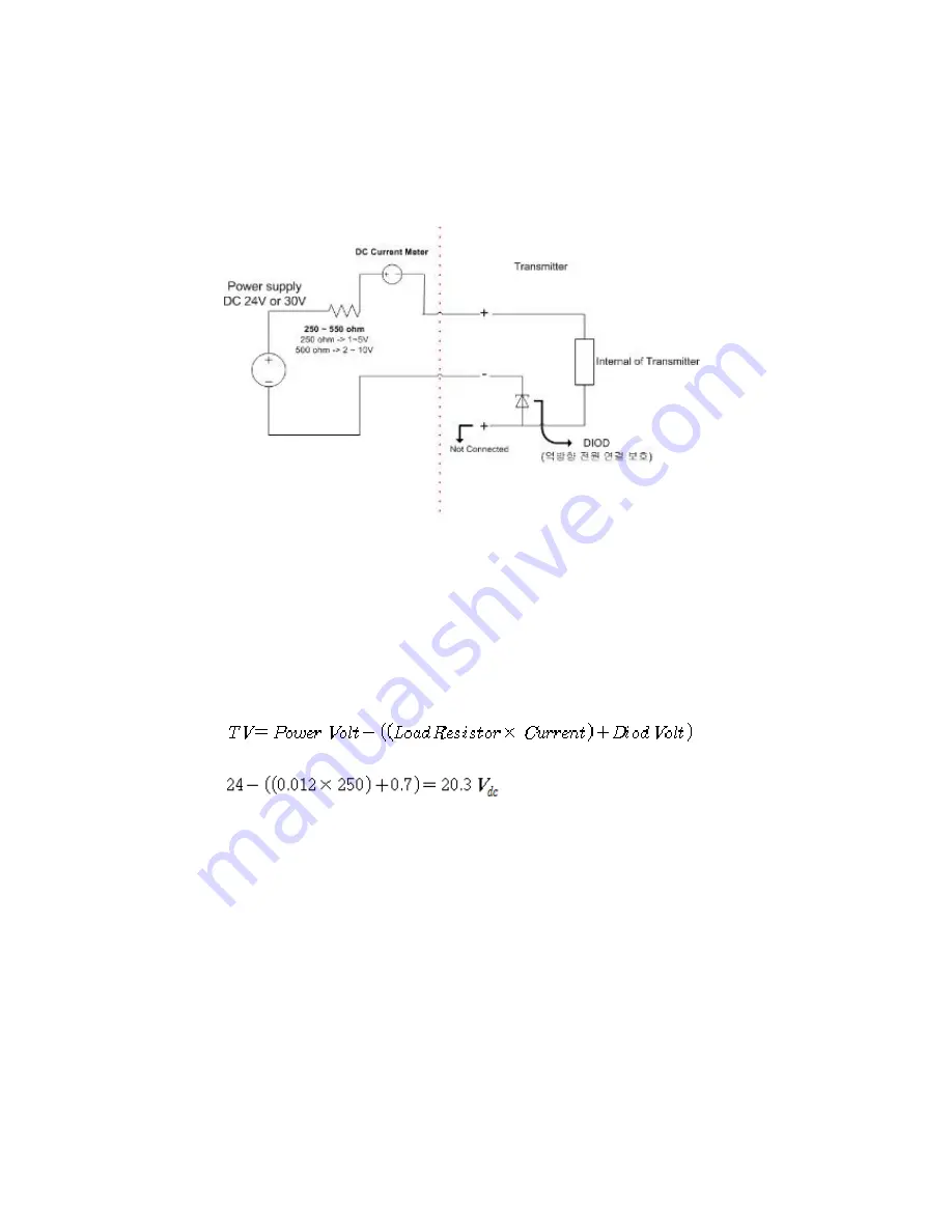
The following voltage below can check the output of the transmitter in the correction
room.
[Figure 12 way to check the output of the transmitter terminal]
Transmitter terminal approval voltage load resistance of the voltage decrease is
decided of the diode's flow. For example, the Transmitter's approval is voltage 24Vdc
and the output electricity is 12mA and with the Load resistance being 250ohm, can lead
to the following voltage of the following Transmitter terminal.
With the following terms, the approved transmitter terminal voltage is actually 20.3 Vdc.
5.4. Board
The electric board built inside the Transmitter is set up as the following.
1) Terminal Board
2) Main & Power Board
3) Analog Board
4) LCD Board (
include in Non-Safety Product
)


