Installation
16
3.3 INTERCONNECTION WITH THE GENERATOR CONTROLLER
The DSEP100 is intended to be placed into the application wiring in such a way as to decouple the
mains and generator supplies in case of a mains failure when in parallel.
Depending upon the requirements of the system, the relay is used to open the mains breaker,
generator breaker or both as described below.
Additionally, any other control logic placed between the DSEP100 and the breakers being controlled
must also be designed with fast operation in mind. The combined time between the DSEP100
detecting the fault, and the time of the breaker opening must be within the specification of the
legislation in place at the site. This legislation differs between countries.
3.3.1 OPEN THE MAINS BREAKER
NOTE: You must ensure that the generator(s) are capable of supplying the remaining load
after the mains breaker has been opened.
It is recommended that the DSEP100 is used to open the mains breaker directly, giving signal to the
opening or tripping coil. This ensures that the decoupling operation occurs as quickly as possible after
the signal to open is given by the DSEP100.
In addition to this, it is recommended that the DSEP100 signal is also given to any other device that
has control over the mains breaker. For example this could be a DSE8620 type controller.
Where connected to a DSE module with control over the mains breaker, this signal is fed into a digital
input configured to “Auxiliary Mains Failure”. This ensures that this controller is informed about the
mains decoupling operation and can take action itself to open the mains breaker.
Additionally, the DSE module must have “Immediate Mains Dropout” enabled. This configures the
controller to open the mains breaker as soon as the input is received from the DSEP100 device.
Failure to do this may result in “Fail To Close” alarms caused by the mains breaker opening under
control of a device other than the DSEP100.
3.3.2 OPEN THE GENERATOR OR COMMON BUS BREAKER
NOTE: You must ensure that the mains supply is capable of supplying the remaining load
after the generator or common bus breaker has been opened.
It is recommended that the DSEP100 is used to open the generator or common bus breaker directly,
giving signal to the opening or tripping coil. This ensures that the decoupling operation occurs as
quickly as possible after the signal to open is given by the DSEP100.
In addition to this, it is recommended that the DSEP100 signal is also given to any other device that
has control over the generator or common bus breaker. For example this could be a DSE8660 type
controller.
Where connected to a DSE module with control over the generator or common bus breaker, this
signal is fed into a digital input configured to “Electrical Trip”. This ensures that this controller is
informed about the mains decoupling operation and can take action itself to open the generator or
common bus breaker.
Failure to do this may result in “Fail To Close” alarms caused by the mains breaker opening under
control of a device other than the DSEP100.
Содержание DSEP100
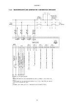
Страница 14: ...Installation 14 3 2 2 MAINS BREAKER AND GENERATOR COMMON BUS BREAKER...
Страница 15: ...Installation 15 3 2 3 ALTERNATE TOPOLOGY WIRING DIAGRAMS...
Страница 41: ...This Page is Intentionally Blank...
Страница 42: ...This Page is Intentionally Blank...


