DSC PC2585 Скачать руководство пользователя страница 8

4

When the transformer is plugged in there should be lights on the keypad and the buzzer connected to the bell terminals

may go ON for a few seconds. The “Armed” light may be ON or OFF the first time the panel is powered. The last armed/
disarmed condition is stored in the EEPROM memory so the panel will always power up in the last armed/disarmed
state. If the “Armed” light is ON, enter the default Master Code [1234] to disarm the panel. If the keypad is not active,
check for the presence of AC power at the “AC” terminals, check the keypad connections and check the panel fuses.

If all the zones are properly connected with double end of line resistors all of the Zone Lights will be OFF. Note that

the panel will arm only if all zones are properly connected with double end of line resistors so that the “Ready” light
is ON. 

NOTE: 

The Fire Zone only requires a single end-of-line resistor. The keypad should beep several times to

indicate acceptance of the Master Code. Enter the Master Code to arm or disarm the panel.

Read the “Keypad Functions” section of this manual or the “End User’s Manual” and enter commands on the keypad

to become familiar with the different commands.

Turn to the “Programming Guide” in this manual and enter a sample program into the panel through the keypad to

become familiar with the programming commands.

Mounting the Panel

Select a dry location close to an unswitched AC source, close to a ground connection and close to the telephone

connection.

Remove printed circuit board, mounting hardware and keypad from cardboard retainer inside panel. Before attaching

cabinet to wall, press the five white nylon printed circuit board mounting studs and the ground connection screw into
cabinet from the back.

Pull all cables into cabinet and prepare them for connection before mounting the circuit board to the back of the

cabinet. Press circuit board down onto mounting studs.
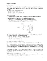
Hook-up Procedure

DO NOT connect transformer or battery until all other wiring has been connected. See power-up procedure.

Connect a ground cable from the cabinet ground connection by the shortest and most direct route to a grounding rod.

Connect zone cables to zone inputs and put double end of line resistors on any unused zones. Connect power wires

for motion detectors to the auxiliary supply.

Install keypads and connect wires to keypad terminals on panel. Connect RJ31-X cord to telephone terminals. Do not

insert plug into RJ31-X jack.

Connect bell or siren to “BELL [+]” and “BELL [-]” terminals. Observe correct polarity for sirens and polarized bells.

Connect 1000

 ½W resistor across terminals to eliminate trouble condition if bell circuit is not being used.

Terminal Connections

AC Power Terminals

Use a 16.5 VAC transformer with a minimum 40 VA rating to supply AC power to the PC2585. The transformer should

not be connected to an outlet that is controlled by a switch. If AC failure occurs it is displayed as a trouble on the keypad
(see “Keypad Functions, [

Q

][2] Trouble Conditions”). It can also be transmitted to the monitoring station as a trouble

condition (see “Programming Guide [

Q

][8]” sections [16] and [17] for alarm and restoral codes and Section [19] for

AC transmission delay).

Auxiliary Power Terminals: AUX+ and AUX-

Two “AUX” terminals are provided to ease wiring congestion at these terminals. The auxiliary power supply can be

used to power motion detectors and other devices requiring 12 VDC. 400mA 12 VDC is available from the “AUX+”
(positive) and “AUX-” (negative) terminals when the PC2585 is used with one keypad. For each additional keypad the
auxiliary supply rating must be reduced by 60mA. The auxiliary supply is fused with the keypad supply at 1 amp.
Auxiliary fuse failure can be transmitted (see [

Q

][8] sections [16] and [17]).

Switched Auxiliary Power Terminals: SW AUX and AUX-

The switched auxiliary supply can be switched off momentarily from the keypad (see “Keypad Functions [

Q

][4]”). The

“SW AUX” terminal is positive and the “AUX-” terminal negative. The 400 mA auxiliary supply rating must be reduced
by any current taken from the switched auxiliary supply. The switched supply shares the same fuse as the auxiliary
supply.

Bell/Siren Terminals BELL [+] and BELL [-]

These terminals are for powering bells or other devices requiring a steady output voltage on alarm. The bell output

is fused for 5 amps. When connecting sirens (speakers with siren driver already built-in), be sure to observe the correct
polarity. Connect the positive lead to the BELL [+] terminal and the negative lead to the BELL [-] terminal.

Содержание PC2585

Страница 1: ...This manual contains information on limitations regarding product use and function and information on the limitations as to liability of the manufacturer The entire manual should be carefully read So...

Страница 2: ...t a security system be reviewed periodically to ensure that its features remain effective and that it be updated or replaced if it is found that it does not provide the protection expected n n n n n A...

Страница 3: ...Master Code 1 12 Auto Arm Time of Day Q 6 Master Code 2 12 Auto Disarm Time of Day Q 6 Master Code 3 12 Quick Arm Q 6 Master Code 4 12 Auto Arm Enable Q 6 Master Code 5 12 Door Chime Q 6 Master Code...

Страница 4: ...ystem Option Code 27 27 Maximum Dialing Attempts per Buffer 27 28 Swinger Shutdown and Transmission Delay Bell Delay 28 29 Communications Format 28 30 Communicator Call Direction Options 31 31 PO1 PO2...

Страница 5: ...279 300 84 mm Weight 6 5 lbs 3 kg Remote Keypad Specifications PC2550RK Four wire QUAD hook up Nominal current draw 60 mA Upto3keypadspersystem recommended Maximum 5 keypads per system refer to Keypa...

Страница 6: ...pervision with LED625T or LCD600T keypads A loss of the AC power supply A supervised circuit trouble condition A telephone line monitoring circuit A bell circuit failure indicates open circuit or fuse...

Страница 7: ...E is a Tamper condition short Zone Connections for Bench Testing Connect the four keypad wires to the control panel as shown in the Hook up Diagram in the back of this manual To completely test the PC...

Страница 8: ...ect zone cables to zone inputs and put double end of line resistors on any unused zones Connect power wires for motion detectors to the auxiliary supply Install keypads and connect wires to keypad ter...

Страница 9: ...ypad for the AUX IN input An alarm on this input is created by applying a positive voltage or by closing a contact between the AUX IN terminal and the positive auxiliary supply See Programming Guide Q...

Страница 10: ...ypad is responding normally connect the battery The red battery lead attaches to the positive battery post and the black battery lead attaches to the negative battery post NOTE THE PC2585 WILL NOT STA...

Страница 11: ...ed for detailed installation instructions It is recommended that additional smoke detectors beyond those required be installed for increased protection The added areas include basement bedrooms dining...

Страница 12: ...Check to see if the Trouble or Bypass light is ON before arming the PC2585 Close all protected doors and windows and stop movement in areas covered by motion detectors Check to see that the Ready lig...

Страница 13: ...s every 10 seconds When the key is pressed the audible indication will stop but the Trouble light will remain ON until the trouble is cleared Trouble conditions can also be transmitted to the monitori...

Страница 14: ...nterrupt the switched auxiliary power supply press Q then hold down 4 for the desired interrupt time When the 4 is released the system returns to the ready mode and the switched auxiliary supply is re...

Страница 15: ...uick Arm enable disable 5 Auto Arm enable disable 6 Door Chime 7 Arm Disarm Memory 8 System Test 9 User Initiated Call up NOTE Enter the time in the 24 hour clock format Enter 00 to 23 for the hour an...

Страница 16: ...time To disable Auto Disarming program an invalid time such as 9999 Quick Arm Q 6 Master Code 4 The Quick Arm feature is enabled by pressing the 4 key while in the User s Function Commands section Wh...

Страница 17: ...Use Code is enabled The One Time Use Code must be used for arming before it is erased Quick Exit Command Q 0 When Armed Entering Q 0 when the system is fully armed will allow the user 2 minutes to ex...

Страница 18: ...0 Mannesman Tally MT81 with serial card 11 Raven 9101 with serial card Configuring the Printer 1 Serial interface 2 Baud rate 1200 other baud rates may be used but Section 49 must be changed according...

Страница 19: ...mally 31 Program with XX00 Program with XX00 32 to 48 Program normally Program normally 49 Printer setup Printer setup 50 Select Language Select Language 90 and 91 Program normally Program normally NO...

Страница 20: ...Code Section 47 Downloading Access Code A 4 digit code must be programmed into this section to allow access to the control panel by the downloading computer Section 48 Downloading Computer Telephone...

Страница 21: ...rmed light will come ON Enter the number of the next Section to be programmed It is not necessary to program all 2 digit numbers in a section After entering a section use the F key to skip to the desi...

Страница 22: ...rnate dialing only When alternate dialing is enabled the system will alternately call the First and Second TelephoneNumbersuntilcommunicationsarecompleted TheSecondTelephoneNumberisassignedtoCommunica...

Страница 23: ...ended Reporting Required 3 digit account code in Sections 02 04 or 06 i e enter 1230 for account code 123 Format code 06 07 08 09 10 depending on receiver type selected in Section 29 Two digit alarm r...

Страница 24: ...s follows C1 C2 C3 C4 C5 C6 C7 C8 Refer to Section 29 Communications Formats for more information The first digit HEX C is used to represent a closing signal this could be another number depending on...

Страница 25: ...ly fuse fails Downloading Lead in Downloading Lead out Refer to the Downloading section of this manual for information on the Downloading Lead in and Lead out codes Keypad Tamper Trouble Keypad Tamper...

Страница 26: ...9 2 Interior Zone is normally used with interior motion detectors and has the standard exit delay time The zone also has the standard entry delay time provided that a Delay Zone has been activated fir...

Страница 27: ...tion on a regular basis to confirm that the communication link to the system is intact The test transmission cycle time is how often in days the test transmission is sent This applies only if the Hour...

Страница 28: ...g the 9 key for about 3 seconds will make the system wait 60 minutes for computer to call Calls received after the 60 minute time will not be answered Default setting 22 Third System Option Code Refer...

Страница 29: ...Zone Light 7 OFF Quick exit disabled ON Quick exit enabled Zone Light 8 OFF Sensor Reset on Arming disabled ON Sensor Reset on Arming enabled When Zone Light 8 is ON the SW AUX output will reset for 5...

Страница 30: ...s disarmed ON 24Hr Bell Always on Tamper On a tamper condition the Bell will always sound Zone Light 6 OFF Tamper follows restore ON Installer Tamper reset If a tamper condition occurs then Installer...

Страница 31: ...led Section 25 Zone Light 3 OFF the system will arm without the 5 second delay for the Battery Test If the system is communicating when an Access Code is entered to arm the system the Battery Test wil...

Страница 32: ...es will not be delayed 29 Communications Format This Section sets the type of format in which Communication Buffers 1 and 2 will communicate For each communication buffer enter two digits from the lis...

Страница 33: ...the event with a particular item i e A reporting code of E3 means restore zone 3 E restore 3 zone 3 4 The following is a list of first digit identifiers that should be used with the Radionics format R...

Страница 34: ...d a beep on the line every 2 seconds after dialing the telephone number Although the event is not identified the recipient of the call is made aware of the alarm Private Line Format Do not use this fo...

Страница 35: ...e Auxiliary Input Zone PO1 can control the PC16OUT Module or any Programmable output option described below PO2 can control a Printer or any Programmable output option described below Programmable Opt...

Страница 36: ...nections section of this manual for details on the Auxiliary Input If a printer is attached to the panel 00 must be selected When option 03 is selected a momentary key closure between the Auxiliary In...

Страница 37: ...Codes Zone and Access Code assignments are programmed in Section 40 through 43 Typically zones and Access Codes are assigned to either Group A or Group B however the system may be programmed so that s...

Страница 38: ...s Before Answer and Downloading Configuration This section is used to enable the Downloading function If Downloading is enabled then the Downloading Access Code must be entered Section 47 and the Pane...

Страница 39: ...1 or 2 will be printed on the printer and communicated to the monitoring station If Zone Light 4 is ON All items whose reporting codes are programmed for Communications Buffer 1 or 2 will be printed...

Страница 40: ...s not entered correctly the keypad will sound a single long tone to indicate the error and the Installer s Lockout will not be disabled NOTE Control panels returned to DSC with the Installer Lockout f...

Страница 41: ..._______________________________________ 2 _____________________________ ________________________________________________________ 3 _____________________________ _______________________________________...

Страница 42: ...Page 18 For 3 digit Account Codes enter 0 for the last digit Where 0 zero is required in the Account Code enter HEX A Q 1 Q 03 Second Telephone Number Page 18 04 Second Account Code Page 18 05 Third...

Страница 43: ...ess Code 3 Closing Access Code 4 Closing Access Code 5 Closing Access Code 6 Closing Access Code 7 Closing Access Code 8 Closing Partial Closing Code 12 Closing Reporting Codes Access Codes 9 16 Page...

Страница 44: ...cess Code 12 Opening Access Code 13 Opening Access Code 14 Opening Access Code 15 Opening Access Code 16 Opening After Alarm Code 15 Priority Alarm and Restoral Reporting Codes Page 21 AUX Input Alarm...

Страница 45: ...r 3 Chime Silent 3 Home Away 4 24 hour Bell 5 24 hour Bell Buzzer 6 24 hour Buzzer 7 Auxiliary Delay 8 Interior Delay 19 System Times Page 23 Default 0 3 0 Entry Delay seconds 0 4 5 Exit Delay seconds...

Страница 46: ...wer Ack Tone 1300Hz ID Panel Answer Ack Tone 23 Fourth System Option Code Page 25 Default Zone Light ON Zone Light OFF OFF Zone Light 1 Send Identified Partial Closings Partial Closings not identified...

Страница 47: ...No keypad timeout OFF Zone Light 4 Keypad Tamper Enabled Keypad Tamper Disabled OFF Zone Light 5 Battery test every 10s Battery test every 4 minutes OFF Zone Light 6 AC Trouble Not Reported AC Troubl...

Страница 48: ...Restorals 1 Group A Access Codes Openings and Closings 1 Group B Access Codes Openings and Closings 1 Priority Alarms and Restorals 1 Maintenance Alarms and Restorals 31 PO1 PO2 and AUX IN Input Optio...

Страница 49: ...a Zone Light is ON that zone may be bypassed using the Q 1 Bypass command Default ON Zone 1 ON Zone 2 ON Zone 3 ON Zone 4 ON Zone 5 ON Zone 6 ON Zone 7 ON Zone 8 37 Access Code Bypass Mask Access Code...

Страница 50: ...ON Access Code 14 ON Access Code 15 ON Access Code 16 39 Keypad Lockout Options Page 33 Default 0 0 Number of attempts to enter a valid code before keypad locks out Enter 00 to disable this feature 1...

Страница 51: ...or OFF press its corresponding number key If the light is OFF when the key is pressed the light will come ON if the light is ON when the key is pressed the light will be shut OFF The default setting...

Страница 52: ...or Communications Buffer 2 will NOT be communicated to the monitoring station but will be printed on the printer If Zone Lights 4 and 5 are OFF All items whose reporting codes are programmed for Commu...

Страница 53: ...AWG 16 AWG 18 AWG 19 AWG 22 AWG 14 2750 838 1375 419 690 210 460 140 345 105 275 83 230 70 195 59 50 100 200 300 400 500 600 700 1740 530 870 265 435 132 290 88 215 65 170 52 140 43 125 38 1090 332 54...

Страница 54: ...L ANY COM TERMINAL ALARM CONTACT 5600 5600 DOUBLE EOL CIRCUIT 2 NORMALLY CLOSED CONTACTS WITH 5600 EOL RESISTORS ANY Z TERMINAL ANY COM TERMINAL ALARM CONTACT TAMPER CONTACT 5600 5600 NORMALLY CLOSED...

Страница 55: ......

Страница 56: ...1997 Digital Security Controls Ltd 1645 Flint Road Downsview Ontario Canada M3J 2J6 Tel 416 665 8460 Fax 416 665 9310 Printed in Canada 29002617 R0...

Страница 57: ...This manual contains information on limitations regarding product use and function and information on the limitations as to liability of the manufacturer The entire manual should be carefully read So...

Страница 58: ...t a security system be reviewed periodically to ensure that its features remain effective and that it be updated or replaced if it is found that it does not provide the protection expected n n n n n A...

Страница 59: ...Master Code 1 12 Auto Arm Time of Day Q 6 Master Code 2 12 Auto Disarm Time of Day Q 6 Master Code 3 12 Quick Arm Q 6 Master Code 4 12 Auto Arm Enable Q 6 Master Code 5 12 Door Chime Q 6 Master Code...

Страница 60: ...ystem Option Code 27 27 Maximum Dialing Attempts per Buffer 27 28 Swinger Shutdown and Transmission Delay Bell Delay 28 29 Communications Format 28 30 Communicator Call Direction Options 31 31 PO1 PO2...

Отзывы: