


49
KEYPAD AND FIRE CIRCUIT WIRING INFORMATION
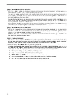
Keypad Hook-up Diagram and Wiring Chart
1
Each keypad has four coloured leads: red (RED), black (BLK), yellow (YEL) and green (GRN). Connect the leads
to the corresponding terminals on the control panel.
2
Up to 5 keypads may be connected in parallel. Do not connect multiple keypads on the same loop.
3
The wiring chart provides the maximum wire run for various wire gauges. Wire run lengths are calculated for the
keypad’s maximum current draw (when all keypad lights are ON).
4
For stand-by loading purposes, it is recommended that a current draw of 20mA per keypad be used. 20mA
represents the control panel in the disarmed state with two zones in alarm.
NOTE: If more that three keypads are
connected, subtract 60mA from the maximum AUX supply for each keypad in excess of three.
NOTE:
If two wires of the same gauge are paralleled, the run length may be doubled. For example, if eight 22AWG
wires (2 RED, 2 BLK, 2 YEL and 2 GRN) are run to the keypad, the run length may be doubled from 540 feet
(164.5 m) to 1080 feet (329 m).
Fire and Bell Circuit Wiring Charts
Loop
Current
mA
AWG
16
AWG
18
AWG
19
AWG
22
AWG
14
2750/838
1375/419
690/210
460/140
345/105
275/83
230/70
195/59
50
100
200
300
400
500
600
700
1740/530
870/265
435/132
290/88
215/65
170/52
140/43
125/38
1090/332
545/166
270/82
180/55
135/41
105/32
90/27
80/24
869/264
435/132
217/66
144/44
108/33
86/26
72/22
62/19
433/131
217/66
144/44
108/33
54/16
43/13
36/11
30/9
Maximum Run to EOL Resistor (ft/m)
BELL LOOP WIRING CHART
Wire
Gauge
15500 / 4724
9740 / 2968
6120 / 1865
4860 / 1481
3840 / 1170
3060 / 932
2420 / 737
AWG14
AWG16
AWG18
AWG19
AWG20
AWG21
AWG22
Maximum Run to
End of Line Resistor
(feet/metres)
ALARM INITIATING LOOP
WIRING CHART
Loop
Current
mA
AWG
16
AWG
18
AWG
19
AWG
22
AWG
14
4750/1448
2375/724
1190/363
790/241
595/181
100
50
200
300
400
1500/457
3000/914
750/229
500/152
375/114
940/287
1880/573
470/143
310/94
235/72
750/229
1500/457
370/113
250/76
185/56
370/113
750/229
185/56
120/37
90/27
Maximum Run to End of Line Relay
(feet/metres)
SMOKE DETECTOR POWER LOOP WIRING CHART
RED BLK YEL GRN
1
2
5
6
7
R
ea
dy
A
rm
ed
M
em
or
y
B
yp
as
s
Tr
ou
bl
e
P
ro
gr
am
Fi
re
3
4
8
1
2
5
6
7
R
ea
dy
A
rm
ed
M
em
or
y
B
yp
as
s
Tr
ou
bl
e
P
ro
gr
am
Fi
re
3
4
8
Wire
Gauge
330 / 100
540 / 164
850 / 259
1000 / 305
1360 / 414
AWG24
AWG22
AWG20
AWG19
AWG18
Maximum Run Length
Keypad to Panel
(feet/metres)
KEYPAD WIRING CHART
Содержание PC2585
Страница 55: ......