


LIMITED WARRANTY
Digital Security Controls Ltd. warrants the original purchaser that for a period of twelve
months from the date of purchase, the product shall be free of defects in materials and
workmanship under normal use. During the warranty period, Digital Security Controls
Ltd. shall, at its option, repair or replace any defective product upon return of the product
to its factory, at no charge for labour and materials. Any replacement and/or repaired
parts are warranted for the remainder of the original warranty or ninety (90) days, which-
ever is longer. The original owner must promptly notify Digital Security Controls Ltd. in
writing that there is defect in material or workmanship, such written notice to be received
in all events prior to expiration of the warranty period.
International Warranty
The warranty for international customers is the same as for any customer within Canada
and the United States, with the exception that Digital Security Controls Ltd. shall not be
responsible for any customs fees, taxes, or VAT that may be due.
Warranty Procedure
To obtain service under this warranty, please return the item(s) in question to the point of
purchase. All authorized distributors and dealers have a warranty program. Anyone re-
turning goods to Digital Security Controls Ltd. must f irst obtain an authorization num-
ber. Digital Security Controls Ltd. will not accept any shipment whatsoever for which
prior authorization has not been obtained.
Conditions to Void Warranty
This warranty applies only to defects in parts and workmanship relating to normal use. It
does not cover:
• damage incurred in shipping or handling;
• damage caused by disaster such as f ire, flood, wind, earthquake or lightning;
• damage due to causes beyond the control of Digital Security Controls Ltd. such as
excessive voltage, mechanical shock or water damage;
• damage caused by unauthorized attachment, alterations, modifications or foreign objects;
• damage caused by peripherals (unless such peripherals were supplied by Digital Secu-
rity Controls Ltd.);
• defects caused by failure to provide a suitable installation environment for the prod-
ucts;
• damage caused by use of the products for purposes other than those for which it was
designed;
• damage from improper maintenance;
• damage arising out of any other abuse, mishandling or improper application of the
products.
Digital Security Controls Ltd.’s liability for failure to repair the product under this war-
ranty after a reasonable number of attempts will be limited to a replacement of the prod-
uct, as the exclusive remedy for breach of warranty. Under no circumstances shall Digital
Security Controls Ltd. be liable for any special, incidental, or consequential damages
based upon breach of warranty, breach of contract, negligence, strict liability, or any
other legal theory. Such damages include, but are not limited to, loss of profits, loss of
the product or any associated equipment, cost of capital, cost of substitute or replace-
ment equipment, facilities or services, down time, purchaser’s time, the claims of third
parties, including customers, and injury to property.
Disclaimer of Warranties
This warranty contains the entire warranty and shall be in lieu of any and all other
warranties, whether expressed or implied (including all implied warranties of mer-
chantability or fitness for a particular purpose) And of all other obligations or li-
abilities on the part of Digital Security Controls Ltd. Digital Security Controls Ltd.
neither assumes nor authorizes any other person purporting to act on its behalf to
modify or to change this warranty, nor to assume for it any other warranty or liabil-
ity concerning this product.
This disclaimer of warranties and limited warranty are governed by the laws of the
province of Ontario, Canada.
WARNING: Digital Security Controls Ltd. recommends that the entire system be com-
pletely tested on a regular basis. However, despite frequent testing, and due to, but not
limited to, criminal tampering or electrical disruption, it is possible for this product to
fail to perform as expected.
Installer’s Lockout
Any products returned to DSC which have the Installer’s Lockout option enabled and
exhibit no other problems will be subject to a service charge.
Out of Warranty Repairs
Digital Security Controls Ltd. will at its option repair or replace out-of-warranty prod-
ucts which are returned to its factory according to the following conditions. Anyone
returning goods to Digital Security Controls Ltd. must f irst obtain an authorization num-
ber. Digital Security Controls Ltd. will not accept any shipment whatsoever for which
prior authorization has not been obtained.
Products which Digital Security Controls Ltd. determines to be repairable will be repaired
and returned. A set fee which Digital Security Controls Ltd. has predetermined and which
may be revised from time to time, will be charged for each unit repaired.
Products which Digital Security Controls Ltd. determines not to be repairable will be
replaced by the nearest equivalent product available at that time. The current market
price of the replacement product will be charged for each replacement unit.
WARNING
Please Read Carefully
Note to Installers
This warning contains vital information. As the only individual in contact with system users, it is your
responsibility to bring each item in this warning to the attention of the users of this system.
System Failures
This system has been carefully designed to be as effective as possible. There are circumstances, how-
ever, involving fire, burglary, or other types of emergencies where it may not provide protection. Any
alarm system of any type may be compromised deliberately or may fail to operate as expected for a
variety of reasons. Some but not all of these reasons may be:
n
n
n
n
n
Inadequate Installation
A security system must be installed properly in order to provide adequate protection. Every installation
should be evaluated by a security professional to ensure that all access points and areas are covered.
Locks and latches on windows and doors must be secure and operate as intended. Windows, doors,
walls, ceilings and other building materials must be of suff icient strength and construction to provide
the level of protection expected. A reevaluation must be done during and after any construction activity.
An evaluation by the fire and/or police department is highly recommended if this service is available.
n
n
n
n
n
Criminal Knowledge
This system contains security features which were known to be effective at the time of manufacture. It
is possible for persons with criminal intent to develop techniques which reduce the effectiveness of
these features. It is important that a security system be reviewed periodically to ensure that its features
remain effective and that it be updated or replaced if it is found that it does not provide the protection
expected.
n
n
n
n
n
Access by Intruders
Intruders may enter through an unprotected access point, circumvent a sensing device, evade detection
by moving through an area of insufficient coverage, disconnect a warning device, or interfere with or
prevent the proper operation of the system.
n
n
n
n
n
Power Failure
Control units, intrusion detectors, smoke detectors and many other security devices require an adequate
power supply for proper operation. If a device operates from batteries, it is possible for the batteries to fail.
Even if the batteries have not failed, they must be charged, in good condition and installed correctly. If a
device operates only by AC power, any interruption, however brief, will render that device inoperative
while it does not have power. Power interruptions of any length are often accompanied by voltage fluctua-
tions which may damage electronic equipment such as a security system. After a power interruption has
occurred, immediately conduct a complete system test to ensure that the system operates as intended.
n
n
n
n
n
Failure of Replaceable Batteries
This system’s wireless transmitters have been designed to provide several years of battery life under normal
conditions. The expected battery life is a function of the device environment, usage and type. Ambient
conditions such as high humidity, high or low temperatures, or large temperature fluctuations may reduce the
expected battery life. While each transmitting device has a low battery monitor which identifies when the
batteries need to be replaced, this monitor may fail to operate as expected. Regular testing and maintenance
will keep the system in good operating condition.
n
n
n
n
n
Compromise of Radio Frequency (Wireless) Devices
Signals may not reach the receiver under all circumstances which could include metal objects placed on or
near the radio path or deliberate jamming or other inadvertent radio signal interference.
n
n
n
n
n
System Users
A user may not be able to operate a panic or emergency switch possibly due to permanent or temporary
physical disability, inability to reach the device in time, or unfamiliarity with the correct operation. It is
important that all system users be trained in the correct operation of the alarm system and that they
know how to respond when the system indicates an alarm.
n
n
n
n
n
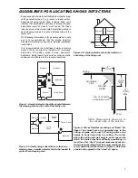
Smoke Detectors
Smoke detectors that are a part of this system may not properly alert occupants of a fire for a number of
reasons, some of which follow. The smoke detectors may have been improperly installed or positioned.
Smoke may not be able to reach the smoke detectors, such as when the fire is in a chimney, walls or roofs,
or on the other side of closed doors. Smoke detectors may not detect smoke from fires on another level of
the residence or building.
Every fire is different in the amount of smoke produced and the rate of burning. Smoke detectors cannot
sense all types of fires equally well. Smoke detectors may not provide timely warning of fires caused by
carelessness or safety hazards such as smoking in bed, violent explosions, escaping gas, improper storage
of flammable materials, overloaded electrical circuits, children playing with matches or arson.
Even if the smoke detector operates as intended, there may be circumstances when there is insufficient
warning to allow all occupants to escape in time to avoid injury or death.
n
n
n
n
n
Motion Detectors
Motion detectors can only detect motion within the designated areas as shown in their respective installa-
tion instructions. They cannot discriminate between intruders and intended occupants. Motion detectors
do not provide volumetric area protection. They have multiple beams of detection and motion can only be
detected in unobstructed areas covered by these beams. They cannot detect motion which occurs behind
walls, ceilings, floor, closed doors, glass partitions, glass doors or windows. Any type of tampering whether
intentional or unintentional such as masking, painting, or spraying of any material on the lenses, mirrors,
windows or any other part of the detection system will impair its proper operation.
Passive infrared motion detectors operate by sensing changes in temperature. However their effective-
ness can be reduced when the ambient temperature rises near or above body temperature or if there are
intentional or unintentional sources of heat in or near the detection area. Some of these heat sources
could be heaters, radiators, stoves, barbeques, fireplaces, sunlight, steam vents, lighting and so on.
n
n
n
n
n
Warning Devices
Warning devices such as sirens, bells, horns, or strobes may not warn people or waken someone sleeping if
there is an intervening wall or door. If warning devices are located on a different level of the residence or
premise, then it is less likely that the occupants will be alerted or awakened. Audible warning devices may be
interfered with by other noise sources such as stereos, radios, televisions, air conditioners or other appliances,
or passing traffic. Audible warning devices, however loud, may not be heard by a hearing-impaired person.
n
n
n
n
n
Telephone Lines
If telephone lines are used to transmit alarms, they may be out of service or busy for certain periods of
time. Also an intruder may cut the telephone line or defeat its operation by more sophisticated means
which may be difficult to detect.
n
n
n
n
n
Insufficient Time
There may be circumstances when the system will operate as intended, yet the occupants will not be
protected from the emergency due to their inability to respond to the warnings in a timely manner. If the
system is monitored, the response may not occur in time to protect the occupants or their belongings.
n
n
n
n
n
Component Failure
Although every effort has been made to make this system as reliable as possible, the system may fail to
function as intended due to the failure of a component.
n
n
n
n
n
Inadequate Testing
Most problems that would prevent an alarm system from operating as intended can be found by regular
testing and maintenance. The complete system should be tested weekly and immediately after a break-
in, an attempted break-in, a fire, a storm, an earthquake, an accident, or any kind of construction
activity inside or outside the premises. The testing should include all sensing devices, keypads, con-
soles, alarm indicating devices and any other operational devices that are part of the system.
n
n
n
n
n
Security and Insurance
Regardless of its capabilities, an alarm system is not a substitute for property or life insurance. An alarm
system also is not a substitute for property owners, renters, or other occupants to act prudently to prevent
or minimize the harmful effects of an emergency situation.
Содержание PC2585
Страница 55: ......