DSC PC1580BABT Скачать руководство пользователя страница 4

G E T T I N G  S T A R T E D

4

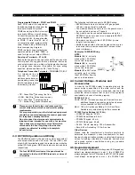
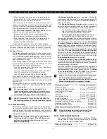
Programmable Outputs – PGM1 and PGM2

Each PGM output is designed so
that when activated by the panel, the
terminal will switch to ground.

PGM2 can sink up to 50 mA of current
to activate LEDs or a small buzzer.
Connect the positive side of the LED
or buzzer to AUX+, the negative side
to PGM2. If more than 50 mA of
current are required, a relay must be
used. Please study PGM wiring in
the accompanying diagram.

PGM1 is a high current output which
operates similar to PGM2. PGM1 is
used for high current output (300mA).

Zone Input Terminals – Z1 to Z6

Each detection device must be connected to a zone on the
control panel. We suggest that one detection device be
connected to each zone; wiring multiple detection devices
to a single zone, however, is possible. For zone wiring
specifics, please see Section 2.8 (“Zone Wiring”).

Telephone Connection Terminals – TIP, RING, T-1, R-1

If a telephone line is
required for central
station communication or
downloading, connect an
RJ-31X telephone jack in
the following manner:

• TIP - Green Wire

incoming line from

• RING - Red Wire

telephone company

• R-1 - Grey Wire

outgoing line to

• T-1 - Brown Wire

house telephone(s)

Please ensure that all plugs and jacks meet the
correct dimension, tolerance and metallic plating
requirements.
For proper operation, no other telephone equipment
should be connected between the control panel and
the telephone company facilities

.

Do not connect the alarm panel communicator to
telephone lines intended for use with a fax machine.
These lines may incorporate a voice filter which
disconnects the line if anything other than fax
signals are detected, resulting in incomplete
transmissions

.

2.3 KEYBUS Operation and Wiring

The KEYBUS is used by the panel to communicate with all
connected modules and vice versa. The red (AUX+) and
black (AUX-) terminals are used to provide power, while the
yellow (YEL) and green (GRN) terminals are clock and data
respectively.

The four KEYBUS terminals of the panel must be
connected to the four KEYBUS terminals or wires of
all modules.

The following restrictions apply to KEYBUS wiring:
• KEYBUS should be run in minimum 22 gauge quad

(0.5mm); two pair twist is preferred.

• The modules should be home run to the panel but can

be connected in series or T-tapped .

• Any module can be connected anywhere along the

KEYBUS. You do not need to run a separate KEYBUS
wire for keypads, etc.

• No module can be more than 1,000'/330m (in wire

length) from the panel.

• Shielded wire should not be used unless wires are run

in an area that presents excessive RF noise or other
such interference.

Example of KEYBUS Wiring
NOTE:

Module (A) 

is correctly

wired within 1,000'/330m
of wire from the panel.

Module (B) 

is correctly

wired within 1,000'/330m
of wire from the panel.

Module (C) 

is NOT wired

correctly as it is further
than 1,000'/330m from the
panel, in wire distance.

2.4 Current Ratings – Modules and

Accessories

In order for the PC1580 system to operate properly, the
power output capabilities of the main control and the
expansion devices must not be exceeded. Use the data
presented below to ensure that no part of the system is
overloaded and cannot function properly.

PC1580 (12 V

DC

)

VAUX: 550 mA.


Includes one keypad. Subtract for each

additional keypad, expansion module and acces-
sory connected to VAUX or KEYBUS.

BELL: 700 mA. Continuous Rating. 3.0 A. Short Term.

Available only with stand-by battery connected.

PC1580 Device Ratings (@ 12 V

DC

)

• LCD5500T Keypad:  50 mA

• PC5400 Serial Module: 65 mA

• PC5506T Keypad: 45 mA

• PC1575RK Keypad: 50 mA

• DLM-4: 160 mA standing / 180 mA transmitter

• Escort: 65 mA standing / 130 mA on-line

Other Devices

Please read the manufacturer’s literature carefully to
determine the maximum current requirements for each
device—during activation or alarm—and include the proper
values for loading calculations. Connected devices must
not exceed system capabilities during any possible
operational mode.

2.5 Keypad Assignment

There are eight available slots for keypads. LED keypads by
default are always assigned to slot 1; the LCD5500T is
always assigned to slot 8. Whereas the PC1575 LED keypad
must always be assigned to slot 1, the PC5506T and

BL

K

RE

D

DSC

RM-1

WH

T

YE

L

GR

N

COM

NC

NO

+AUX

PGM1

(ANY OUTPUT

TERMINAL)

RING TIP R - 1 T-1 EGND

GR

Y

BRN

GR

N

RED

TO

TELEPHONE

COMPANY

TO

PREMISE

TELEPHONE

RJ31X
TELEPHONE
PLUG

Содержание PC1580BABT

Страница 1: ...d Transmissions to Each Telephone Number System Introduction S E C T I O N 1 System Supervision Features The PC1580 continuously monitors a number of possible trouble conditions including AC Power Fai...

Страница 2: ...s as well as surveillance costs thus improving the overall security protection For more information regarding the Downlook Video Transmission Module please consult the DLM 1 DLM 4 Installation Manuals...

Страница 3: ...he various programmable features which options are available and how they function The Programming Worksheets pages 25 33 should be filled out completely before attempting to program the system Step 1...

Страница 4: ...estrictions apply to KEYBUS wiring KEYBUS should be run in minimum 22 gauge quad 0 5mm two pair twist is preferred The modules should be home run to the panel but can be connected in series or T tappe...

Страница 5: ...ons There are several different ways in which zones may be wired depending on which programming options have been selected Please refer to the following diagrams to study each type of individually sup...

Страница 6: ...MINIMUM 18 AWG WIRING IS REQUIR FOR RESIDENTIAL FIRE ALARM SYST TO ZONE Z TERMINAL PROGRAMMED FOR FIRE TO ANY COM TERMINAL A U X B E L L 1 P G M 2 2 8 5 Keyswitch Zone Wiring If PGM2 has been program...

Страница 7: ...ass interior zones manually When the system is armed using a valid user code if any zones on the system have been programmed as Stay Away zones the Bypass light will turn ON The panel will then monito...

Страница 8: ...ill be ON When using an LCD keypad the trouble conditions will be listed on the display the user must simply use the arrow keys to scroll through the list of present trouble conditions The various tro...

Страница 9: ...ccess code 1 One Master Code Access codes 2 to 6 Five User Codes All access codes have the ability to arm or disarm the system and can activate the PGM Outputs using the 7 1 Access Code and 7 2 comman...

Страница 10: ...e the arrow keys to scroll to the desired contrast level and press the key to exit Keypad Beeper Control The LCD keypad will allow you to select from 21 different keypad beeper tones Use the arrow key...

Страница 11: ...in Function Keys Section 3 5 05 9 No Entry Delay Arm Once this function key is pressed the user must enter a valid user code The system will arm and remove the entry delay from the system when the ex...

Страница 12: ...amming Decimal Data A set number of programming boxes are allotted for each section requiring decimal data e g codes telephone numbers If a digit is entered for each program box the panel will automat...

Страница 13: ...one Light 4 8 Add up the values for the zone lights to determine the number displayed for example no zone lights 0 all 4 zone lights 15 HEX F Press any of the Emergency Keys Fire Auxiliary or Panic to...

Страница 14: ...ll cause an instant alarm if it is violated when the panel is armed Typically this zone is used for windows patio doors or other perimeter zones 04 Interior Zone This zone will not cause an alarm if v...

Страница 15: ...hime This attribute determines whether or not the zone will activate the chime feature see Section 3 4 4 Door Chime On Off Bypass Enable This attribute determines whether or not the zone can be manual...

Страница 16: ...es The panel can be programmed to report events to the central station by sending the Reporting Code programmed for a particular event Reporting codes can be one or two digits and can use HEX digits A...

Страница 17: ...e Alarm Reporting Code during short power outages the panel will not send the signal unless AC power is lost for the amount of minutes programmed for the AC Failure Communication Delay The AC Failure...

Страница 18: ...rmats 1 The digit 0 will send no pulses and is used as a filler 2 When programming account numbers enter four digits When programming a three digit account number the fourth digit must be programmed a...

Страница 19: ...ing If the Downloading Answer option is enabled or during the first six hours after power up the panel will answer calls for downloading when the programmed Number of Rings is heard by the panel If th...

Страница 20: ...24 Hour Latching Zones This output will activate for alarm conditions only Pre alerts or delays will not activate the output This output should only be activated for all audible alarms or medical con...

Страница 21: ...porting Codes Section 44 TLM Trouble Delay Section 62 Option 1 5 12 Siren Supervision The panel supervises the Bell output If an open condition is detected or if the fuse is blown the panel will immed...

Страница 22: ...il the exit delay expires The keypad will beep rapidly for the last 10 seconds of exit delay to warn the user that the system is about to arm For commercial applications the Bell Squawk on Exit Delay...

Страница 23: ...eys are pressed for 30 seconds The keys however will remain backlit The panel will turn the lights back on when any key is pressed or when the entry delay begins or if an audible alarm occurs Keypad B...

Страница 24: ...following 1 Enter the Installer s Programming mode 2 Enter the appropriate programming section XY 3 Enter the Installer s Code 4 Re enter the appropriate programming section XY The panel will take a f...

Страница 25: ...eypad 3 I___________________________ __________________I I______________________________________ _ _ _ _ _ _ __ _ _ _ _ _ _ _ _ _ _ _ _ _ _ _ _ _ _ _ _ _ _ _ _ _ _ _ _ _ _ _ _ _ _ _ _ _ _ _ _ _ _ _ _...

Страница 26: ...I________I I________I I________I I________I KEYPAD 6 I________I________ I I________I I________I I________I I________I I________I KEYPAD 7 I________I________ I I________I I________I I________I I______...

Страница 27: ...Trouble Output 28 Silent 24 Hour PGM2 Only 09 Entry Delay Follower 29 Audible 24 Hour PGM2 Only 10 Exit Delay Follower 11 TLM and Alarm 12 Police Code Follower 07 Keypad Lockout Options Section 5 20 K...

Страница 28: ...Y Y N N Y Y Y Y Y Y Y Y Y Y N Option 3 Chime N Y Y Y N N N N N N N N N N N N N N N N N N N N Option 4 Force N N N N N Y Y N N N N N N N N N N N N N N N N Y Option 5 Bypass N Y Y Y Y Y Y N N Y Y N N N...

Страница 29: ...Codes I_______I_______ I Zone 1 I_______I_______ I Zone 4 I_______I_______ I Opening After Alarm I_______I_______ I Zone 2 I_______I_______ I Zone 5 I_______I_______ I Zone 3 I_______I_______ I Zone 6...

Страница 30: ...orting Codes Section 5 7 Communicator Reporting Codes I_______I_______ I Phone Number 1 Failure to Communicate I_______I_______ I General Zone Fault Alarm I_______I_______ I Phone Number 2 Failure to...

Страница 31: ...programmed 5 6 OFF I_______I 6 Restorals on Bell Time out Restorals Follow Zones 5 7 2 61 Second Communicator Option Code Default Option ON OFF Section OFF I_______I 1 Closing Confirmation Enabled Cl...

Страница 32: ...n 5 9 Downloading Default 1580 I_______I_______I______ _ I _ ______I Enter 4 Hexadecimal Digits 74 Panel Identification Code Section 5 9 Downloading Default 1580 I_______I_______I______ _ I _ ______I...

Страница 33: ..._______I 2 Handshake from Printer No Handshake OFF I________I 3 80 Column Printer 40 Column Printer OFF I________I 4 300 Baud Enabled Disabled OFF I________I 5 1200 Baud Enabled Disabled ON I________I...

Страница 34: ...cksum bad 3 A4 ROM checksum bad 3 A5 System Reset 3 A6 Panel prog changed 3 A7 Self test failure 3 A8 System Shutdown 3 A9 Battery Test Failure 3 1A Ground Fault Sounder Relay Troubles 3 2A Sounder Re...

Страница 35: ...XX 24 Hr Emergency Zone Alarm Restore QA XX QH XX 24 Hr Sprinkler Zone Alarm Restore SA XX SH XX 24 Hr Water Zone Alarm Restore WA XX WH XX 24 Hr Freeze Zone Alarm Restore ZA XX ZH XX 24 Hr Latching T...

Страница 36: ...nue from Step 2 until all Labels are programmed 01 to 06 Zone Labels 14 Characters Default to 33 Fire Alarm Label 14 Characters 34 System Label 14 Characters Default Default 40 Utility Output Label 14...

Страница 37: ...ys disabled OFF I_______ I 4 8 For Future Use 65 Fourth User Display Mask Default Option ON OFF ON I_______ I 1 User Initiated Call up Prompt ON User Initiated Call up Prompt OFF ON I_______ I 2 Last...

Страница 38: ...for persons with criminal intent to develop techniques which reduce the effectiveness these features It is important that a security system be reviewed periodically to ensure that its featu remain ef...

Страница 39: ...Panel Wiring Diagram TM Incorrect connections may result in fuse failure or improper operation Inspect wiring and ensure connections are correct before applying power Do not route any wiring over circ...

Страница 40: ...PROVED for connection to telecommunication systems specified in the instructions for use subject to the conditions set out in them S 5054 3 W 504203 DSC PC1580 REN 1 5 London office DSC Security Produ...

Страница 41: ...N G This manual contains information on limitations regarding product use and function and information on the limitations as to liability of the manufacturer The entire manual should be carefully read...

Страница 42: ...the integral modem or call setup equipment to contravene the requirements of the standards for approval as designated All apparatus connected to this equipment and thereby connected directly or indire...

Страница 43: ...5 2 7 Removing Modules 5 2 8 Zone Wiring 5 2 8 1 Normally Closed NC Loops 5 2 8 2 Single End Of Line EOL Resistors 5600 5 2 8 3 Double End of Line DEOL Resistors 5 2 8 4 Fire Zone Wiring Four Wire Smo...

Страница 44: ...nd Sur Gard 4 8 1 Communications Format 18 5 8 2 Pulse Formats 18 5 8 3 Contact ID 18 5 8 4 SIA 18 5 8 5 Pager Format 19 5 9 Downloading 19 5 10 PGM Output Options 19 5 11 Telephone Line Monitor TLM 2...

Отзывы: