


S
Y
S
T
E
M
V
I
N
T
R
O
D
U
C
T
I
O
N
2
All touch tone phones in the home also become system
keypads. For example, at bedtime, the phone beside the bed
can be used to arm the system. The addition of the
ESCORT5580 may reduce the cost of the overall installation,
eliminating the need for additional keypads and the labour of
running wires.
The ESCORT5580 will also act
as a tutor for the system. By
using clear, easy to understand
sentences, the voice module
helps guide the user through
functions they may otherwise
find difficult to navigate. Programmable zone labels (up to
6 words each from our library of over 240 words) makes the
system even easier to use.
The module also has a built-in power line control interface
and can control up to 32 power line control devices for
lighting and temperature control, giving you the power to
add home automation in a very cost effective manner.
Devices can be activated individually, as a group, by
schedule or can be activated when an event occurs on the
system, such as an alarm.
These are just a few of the applications available with the
addition of the ESCORT5580 module. For more information,
please refer to the ESCORT5580 Installation Manual.
1.2.3 PC5400 Printer Module
This module will give you the
added advantage for the
commercial customers who
like the idea of a permanent
record of openings and
closing but are put off by the
additional monthly
monitoring charge. In addition, as reports are generated in
real-time, the customer will not have to wait for a monthly
report form the monitoring station.
The PC5400 Printer Module will allow the panel to print out
all events that occur on the system to any serial printer. The
printout will contain the time, date and the event that occurred
(see Section – 5.25 “On-site Printer”).
1.2.4 Downlook Video Transmission Module
The Downlook Still-Frame Video Transmission Module (DLM-
1/DLM-4) is the ideal solution for all business and residential
environments which require visual surveillance but where
the presence of on-site security personnel is impossible,
undesirable or unaffordable.
Downlook is the smart and inexpensive way to add visual
backup to your regular remote alarm signalling system,
meeting your demand for tighter security on a tight budget.
The added visual protection will reduce the incidence of
false alarms as well as surveillance costs, thus improving
the overall security protection.
For more information regarding the Downlook Video
Transmission Module, please consult the DLM-1/DLM-4
Installation Manuals.
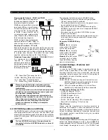
1.2.5 Cabinets
Several different cabinets are available for the PC1580
modules. They are as follows:
PC5003C Cabinet
Control cabinet for the PC1580 main panel. Dimensions
288mm x 298mm x 78mm / 11.3” x 11.7” x 3” approximately.
PC5004C Cabinet
Cabinet to house the Escort5580 Module or the PC5400
Printer Module. Dimensions 229mm x 178mm x 65mm / 9”
x 7” x 2.6” approximately.
1.3 Out of the Box
Please verify that each of the following components is
included in your system:
• one PC1580 control cabinet
• one PC1580 control circuit board
• one keypad (LED keypad or LCD keypad)
• one Installation Manual including Programming
Worksheets
• one Instruction Manual for the end user
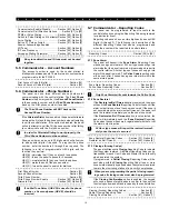
• one hardware pack consisting of:
- four plastic circuit board standoffs
- twelve 5600
Ω
(5.6K) resistors
- one 2200
Ω
(2.2K) resistors
- one 1000
Ω
(1K) resistor
- EGND Assembly
- one cabinet door plug
• 220V to16.5V AC transformer with fuseblock
• two yellow safety hazard warning labels to be applied by the
installer
Enclosed 240V AC Warning Labels
The Health & Safety (Signs and Signals) Regulations state
that warning signs must be displayed to warn people to be
careful to take precautions where a hazard exits.
These signs also comply to the Electricity at Work Regulation
1989 and BS5378.
The Regulations for Electrical Installation (16 Edition) Section
514-10 Warning Notice Voltage.
Every Item of Equipment or enclosure within which a voltage
exceeding 250 Volts exists, and where the presence of such
a voltage would not normally be expected, shall be so
arranged that before access is gained to a live part, a
warning of the maximum voltage present is clearly visible.
It is recommended that one of the enclosed warning stickers
be attached to the external area of the control panel housing
to give indication of voltage before access is gained to the
transformer area. The second enclosed warning sticker
should be placed on the front plate of the unswitched fuse
unit to give indication of mains connection within.
DSC accepts no responsibility for the non use of these
warning labels and can confirm that it is the responsibility of
the installation engineers to attach them to the required
devices during the installation process. The warning labels
are enclosed to be used in accordance with the Health and
Safety regulations and also the electricity at work act 1989.