WJ-8611 DIGITAL VHF/UHF RECEIVER
5-14 CIRCUIT
DESCRIPTIONS
The Control Processor section maintains control over all receiver
operations. It consists of an MC 68331 16-bit microprocessor,
Programmable Flexible Logic circuits, and a dedicated MC 68HC711D3
gain control microprocessor. This section sends control data to the RF
Tuner Assembly (A3) by way of a serial control bus, down-loads the
operating programs for the two DSP processors, via the 16-bit data bus
contained on the Digital Control PC Assembly (A2), and provides a
control interface to communicate with the receiver’s front panel controls
and rear panel RS-232 Serial or IEEE-488 Parallel interfaces. It also
configures the two programmable Flexible Logic integrated circuits that
provide the interfacing logic between the various digital processing
circuits. On receiver power up, the control processor configures the two
programmable Flexible Logic integrated circuits that provide the
interfacing logic between the various digital processing circuits. It then
downloads the operating programs for the two DSP processors, and sends
receiver parameter data to the DSP Processors. The DSP processors then
use this data to determine the processing tasks associated with signal
conditioning and demodulation of the intelligence.
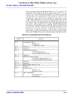
Two DIP switches (S1 and S2), contained in the Control Processor section,
permit the WJ-8611 Receiver to be configured for its intended operating
environment. On receiver power up, the control processor reads these
switches to determine the operating configuration of the receiver. Switch
S2 selects the default configuration of the receiver’s remote interface. It
selects the type interface that will be active (IEEE-488 or RS-232) and
determines the receiver’s IEEE-488 bus address or the RS-232 baud rate.
When the IEEE-488 mode is selected, the bus address can be set to a value
of from 0 to 30, using switch positions 1 to 5. In the RS-232 mode, the
9600-baud rate or a user-defined baud rate can be selected by switch
position 8 (the user-defined baud rate defaults to 38400 baud unless
otherwise configured). Switch position 7 determines which of the
interfaces will be selected.
Switch S1 determines the operating mode that the receiver assumes at
power up and enables or disables front panel control of the receiver’s
IEEE-488 address selection. Switch position 1 determines if the receiver
powers up in the normal operating mode (switch closed) or if the
configuration mode is active (switch open). Position 6 of S1 permits the
receiver’s IEEE-488 address to be changed at the front panel (switch
closed). If this switch is open, address changes can only be performed at
DIP switch S2.
Table 5-5
provides a summary of the S1 and S2 switch
configurations.
Control over the RF Tuner Assembly (A3) operations is maintained by the
serial control bus, consisting of the RFB CLK, RFB DATA, and RFB STB
serial data and timing lines (J1, pins 19, 20, and 21), and the RFB A0, RFB
A1, and RFB A2 parallel control lines (J1, pins 23, 24, and 25). These
lines provide the data for synthesizer tuning and preselector band selection.
It also controls the tuning of the Tracking Preselector in the RF Tuner
Assembly (A3) via the preselector tuning voltage line PRETV (J1 pin 10).
Courtesy of http://BlackRadios.terryo.org
Содержание WJ-8611
Страница 3: ...A B blank Courtesy of http BlackRadios terryo org...
Страница 4: ...THIS PAGE INTENTIONALLY LEFT BLANK Courtesy of http BlackRadios terryo org...
Страница 19: ...1 i SECTION 1 GENERAL DESCRIPTION Courtesy of http BlackRadios terryo org...
Страница 20: ...1 ii THIS PAGE INTENTIONALLY LEFT BLANK Courtesy of http BlackRadios terryo org...
Страница 28: ...WJ 8611 DIGITAL VHF UHF RECEIVER 1 8 GENERAL DESCRIPTION NOTES Courtesy of http BlackRadios terryo org...
Страница 29: ...2 i SECTION 2 INSTALLATION Courtesy of http BlackRadios terryo org...
Страница 30: ...2 ii THIS PAGE INTENTIONALLY LEFT BLANK Courtesy of http BlackRadios terryo org...
Страница 47: ...3 i SECTION 3 LOCAL OPERATION Courtesy of http BlackRadios terryo org...
Страница 48: ...3 ii THIS PAGE INTENTIONALLY LEFT BLANK Courtesy of http BlackRadios terryo org...
Страница 84: ...WJ 8611 DIGITAL VHF UHF RECEIVER 3 36 LOCAL OPERATION NOTES Courtesy of http BlackRadios terryo org...
Страница 85: ...4 i SECTION 4 REMOTE CONTROL Courtesy of http BlackRadios terryo org...
Страница 86: ...4 ii THIS PAGE INTENTIONALLY LEFT BLANK Courtesy of http BlackRadios terryo org...
Страница 119: ...5 i SECTION 5 CIRCUIT DESCRIPTIONS Courtesy of http BlackRadios terryo org...
Страница 120: ...5 ii THIS PAGE INTENTIONALLY LEFT BLANK Courtesy of http BlackRadios terryo org...
Страница 142: ...WJ 8611 DIGITAL VHF UHF RECEIVER 5 22 CIRCUIT DESCRIPTIONS NOTES Courtesy of http BlackRadios terryo org...
Страница 143: ...6 i SECTION 6 MAINTENANCE Courtesy of http BlackRadios terryo org...
Страница 144: ...6 ii THIS PAGE INTENTIONALLY LEFT BLANK Courtesy of http BlackRadios terryo org...
Страница 167: ...7 i SECTION 7 REPLACEMENT PARTS LIST Courtesy of http BlackRadios terryo org...
Страница 168: ...7 ii THIS PAGE INTENTIONALLY LEFT BLANK Courtesy of http BlackRadios terryo org...
Страница 243: ...A i APPENDIX A 8611 SM SIGNAL MONITOR OPTION Courtesy of http BlackRadios terryo org...
Страница 244: ...A ii THIS PAGE INTENTIONALLY LEFT BLANK Courtesy of http BlackRadios terryo org...
Страница 267: ...FP i FOLDOUTS Courtesy of http BlackRadios terryo org...
Страница 268: ...FP ii THIS PAGE INTENTIONALLY LEFT BLANK Courtesy of http BlackRadios terryo org...
Страница 298: ...Courtesy of http BlackRadios terryo org...
Страница 300: ...Courtesy of http BlackRadios terryo org...
Страница 301: ...Courtesy of http BlackRadios terryo org...

