WJ-8611 DIGITAL VHF/UHF RECEIVER
5-12 CIRCUIT
DESCRIPTIONS
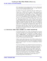
STEP, LOCK2 RES, and LOCK2 TRANS lock indications are summed
with the LOCK3 indication from the 3rd LO synthesizer to provide the 2nd
LOCK status indication to the Digital Control PC Assembly (A2) (A2P3,
pin 31). Three Lock Detect LEDs also provide a visual indication of the
synthesizer status. During normal 2nd LO operation, the LOCK2 STEP
LED (DS3), the LOCK2 RES LED (DS1), and the LOCK2 TRANS LED
(DS2) should all be extinguished.
Operating power and control data from the Digital Control PC Assembly
(A2) is routed into the 2nd LO/2nd Converter PC Assembly (A3A2), via
the A3A2P3 interface cable. It is then distributed to the various circuits in
the 2nd LO/2nd Converter and in the 1st LO/1st Converter PC Assembly
(A3A1). The control data from the Digital Control PC Assembly (A2)
consists of an analog 0 to +5V preselector tracking voltage (PRE TV), a 6-
bit parallel control bus for RF and IF gain control (RF 16, and IF
1/2/4/8/16), and a serial control bus for synthesizer tuning and preselector
band selection.
The serial control bus provides serial data into the 2nd LO/2nd Converter
PC Assembly (A3A2) where it is directed to the appropriate circuits. The
serial data, consisting of a series of 8-bit control words, is provided at pin
20 of cable A3A2P3 (RFB DATA). Its serial transfer is synchronized with
the data clock at A3A2P3 pin 19 (RFB CLK). During the data transfer, the
data and clock signals are directed to all of the circuits in the RF Tuner
Assembly (A3). No circuit responds to the data until the strobe line (RFB
STB) at A3A2P3, pin 21, is pulsed. The strobe line is maintained at a
logic “1” state until the data has been transferred. At the completion of the
transfer of a data block, a logic “0” pulse on the RFB STB line causes the
intended circuit to accept and respond to the new control data. The RFB
A0, A1, and A2 lines entering at A3A2P3, pins 23, 24, and 25, determine
the actual circuit that responds to the data. These lines direct the RFB STB
pulse to the intended circuit, assuring that the proper circuit accepts the
data. They form a 3-bit binary word that directs the strobe to the
appropriate circuit, as illustrated in
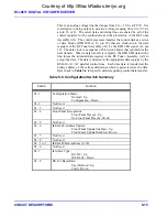
Table 5-4
.
Table 5-4. Serial Control Bus Data Distribution
RFB Control
Description
A2 A1 A0
Signal
Responding
Circuit
0
0
0 PRESEL STB Preselector band or bypass selection.
1
0
0 EN4
Reference synthesizer tuning data, when external reference is present.
0
1
0 STB3
3rd LO synthesizer tuning data.
1
1
0 1ST LO STB 1st LO synthesizer tuning data to the 1st LO/1st Converter.
0
0
1 STB2 RES
2nd LO synthesizer resolution loop tuning data.
1
0
1 STB2 STEP 2nd LO synthesizer coarse loop tuning data.
0
1
1 REF
Reference synthesizer enable (1)/disable (0).
1 1 1 Not
Used
Courtesy of http://BlackRadios.terryo.org
Содержание WJ-8611
Страница 3: ...A B blank Courtesy of http BlackRadios terryo org...
Страница 4: ...THIS PAGE INTENTIONALLY LEFT BLANK Courtesy of http BlackRadios terryo org...
Страница 19: ...1 i SECTION 1 GENERAL DESCRIPTION Courtesy of http BlackRadios terryo org...
Страница 20: ...1 ii THIS PAGE INTENTIONALLY LEFT BLANK Courtesy of http BlackRadios terryo org...
Страница 28: ...WJ 8611 DIGITAL VHF UHF RECEIVER 1 8 GENERAL DESCRIPTION NOTES Courtesy of http BlackRadios terryo org...
Страница 29: ...2 i SECTION 2 INSTALLATION Courtesy of http BlackRadios terryo org...
Страница 30: ...2 ii THIS PAGE INTENTIONALLY LEFT BLANK Courtesy of http BlackRadios terryo org...
Страница 47: ...3 i SECTION 3 LOCAL OPERATION Courtesy of http BlackRadios terryo org...
Страница 48: ...3 ii THIS PAGE INTENTIONALLY LEFT BLANK Courtesy of http BlackRadios terryo org...
Страница 84: ...WJ 8611 DIGITAL VHF UHF RECEIVER 3 36 LOCAL OPERATION NOTES Courtesy of http BlackRadios terryo org...
Страница 85: ...4 i SECTION 4 REMOTE CONTROL Courtesy of http BlackRadios terryo org...
Страница 86: ...4 ii THIS PAGE INTENTIONALLY LEFT BLANK Courtesy of http BlackRadios terryo org...
Страница 119: ...5 i SECTION 5 CIRCUIT DESCRIPTIONS Courtesy of http BlackRadios terryo org...
Страница 120: ...5 ii THIS PAGE INTENTIONALLY LEFT BLANK Courtesy of http BlackRadios terryo org...
Страница 142: ...WJ 8611 DIGITAL VHF UHF RECEIVER 5 22 CIRCUIT DESCRIPTIONS NOTES Courtesy of http BlackRadios terryo org...
Страница 143: ...6 i SECTION 6 MAINTENANCE Courtesy of http BlackRadios terryo org...
Страница 144: ...6 ii THIS PAGE INTENTIONALLY LEFT BLANK Courtesy of http BlackRadios terryo org...
Страница 167: ...7 i SECTION 7 REPLACEMENT PARTS LIST Courtesy of http BlackRadios terryo org...
Страница 168: ...7 ii THIS PAGE INTENTIONALLY LEFT BLANK Courtesy of http BlackRadios terryo org...
Страница 243: ...A i APPENDIX A 8611 SM SIGNAL MONITOR OPTION Courtesy of http BlackRadios terryo org...
Страница 244: ...A ii THIS PAGE INTENTIONALLY LEFT BLANK Courtesy of http BlackRadios terryo org...
Страница 267: ...FP i FOLDOUTS Courtesy of http BlackRadios terryo org...
Страница 268: ...FP ii THIS PAGE INTENTIONALLY LEFT BLANK Courtesy of http BlackRadios terryo org...
Страница 298: ...Courtesy of http BlackRadios terryo org...
Страница 300: ...Courtesy of http BlackRadios terryo org...
Страница 301: ...Courtesy of http BlackRadios terryo org...

